Heavy duty vehicles diagnostics
In this Article:
- 1. Diagnostics of O&K excavator
- 2. Diagnostics of 2012 Iveco Stralis heavy-duty truck
- 3. Isuzu NQR truck
- 4. Diagnosing fuel system failures on Kalmar CSC340 straddle carriers
- 5. Volvo FH13 long-haul truck
- 6. Mercedes-Benz Actros 460 heavy-duty truck
- 8. Freightliner Columbia 112/120 heavy-duty semi-truck
- 9. The Best oscilloscope for heavy-duty vehicles
Diagnosing modern heavy-duty vehicles requires not only advanced equipment but also a deep understanding of how complex mechanical, hydraulic, and electronic systems interact under real-world loads. The materials presented on this page are based on the practical experience of a highly skilled colleague who has spent years working with the USB Autoscope IV diagnostic device. His hands-on approach, careful methodology, and professional insights form the foundation of the explanations, examples, and case studies you’ll find here. This knowledge is not theoretical—it comes directly from fieldwork on trucks, excavators, straddle carriers, and other heavy-duty vehicles where accuracy and reliability are essential.
This page aims to make that expertise accessible, helping both beginners and seasoned technicians better understand diagnostic strategies, waveform analysis, and effective troubleshooting techniques using the USB Autoscope IV.

1. Diagnostics of O&K excavator
Many of my subscribers noticed my recent post about repairing an excavator and asked an important question:
“What exactly can be checked on an excavator using the USB Autoscope IV?”
The answer is simple — a lot.
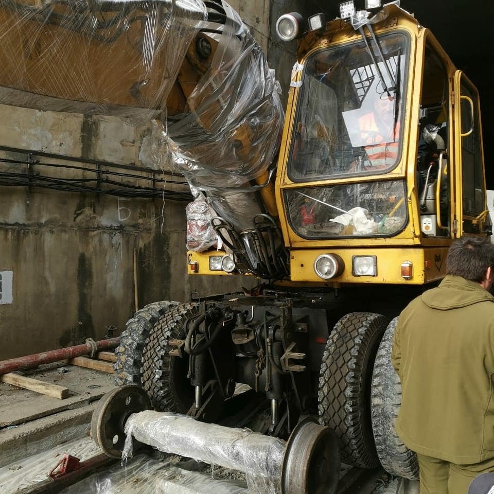
This device can be used anywhere there is a need to inspect signals from sensors, data buses, actuators, or microprocessors. Although many people associate it primarily with automotive diagnostics, the USB Autoscope IV is a universal oscilloscope perfectly suited for heavy equipment as well.
-

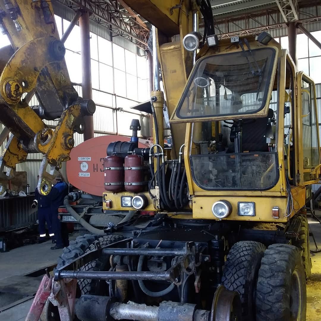
- O&K excavator undergoing electronic diagnostics
-

- USB Autoscope IV used for O&K excavator repair
-
- O&K excavator undergoing signal-level diagnostics with the USB Autoscope IV automotive oscilloscope
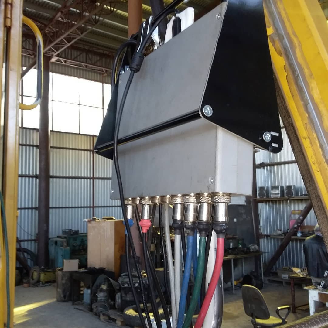
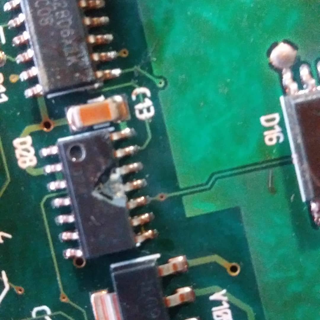
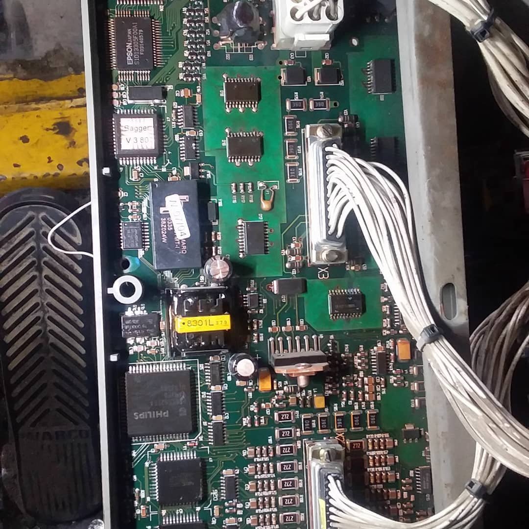
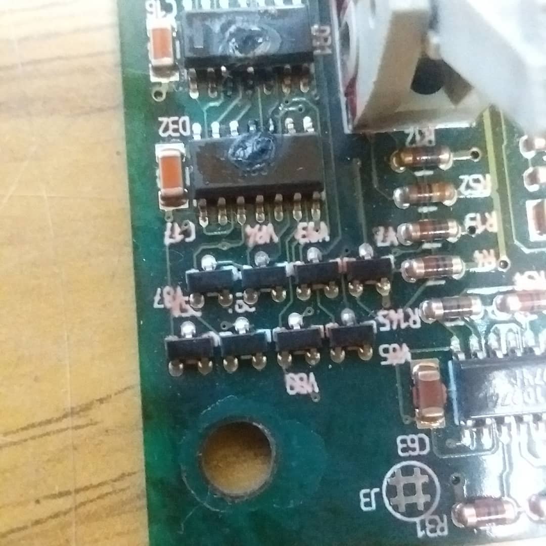
In this particular case, the failure was located in the most unexpected and “exciting” place — the control unit. Taking the opportunity, I want to express my gratitude to the team who developed and continue improving both the Autoscope device and its software. We rely on it with confidence and success.
-
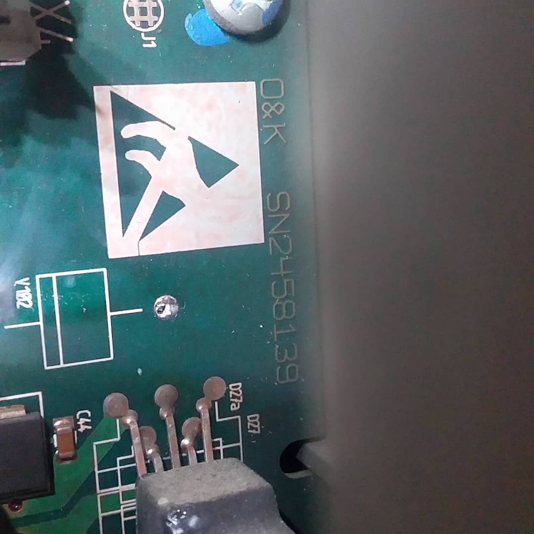
- O&K SN2458139 control board ECU repair
-
- O&K SN2458139 control board repair
-
- Technician preparing the SN2458139 ECU board from an O&K excavator for detailed diagnostic and repair
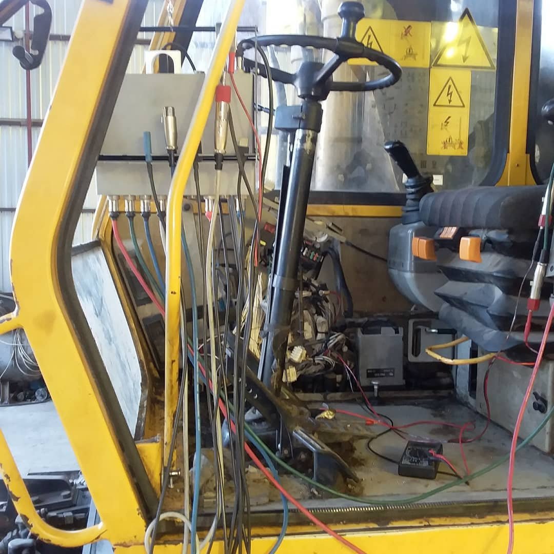
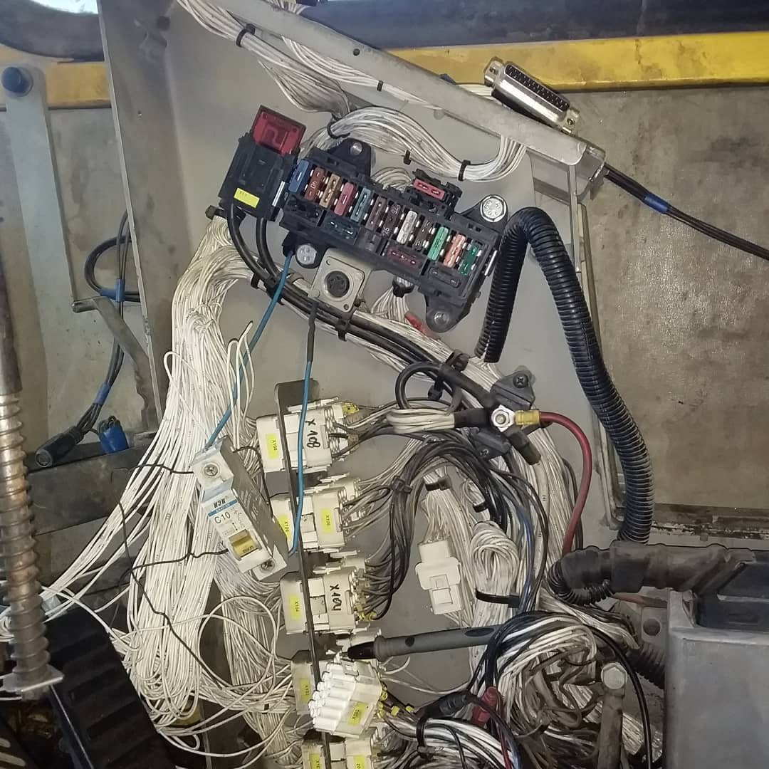
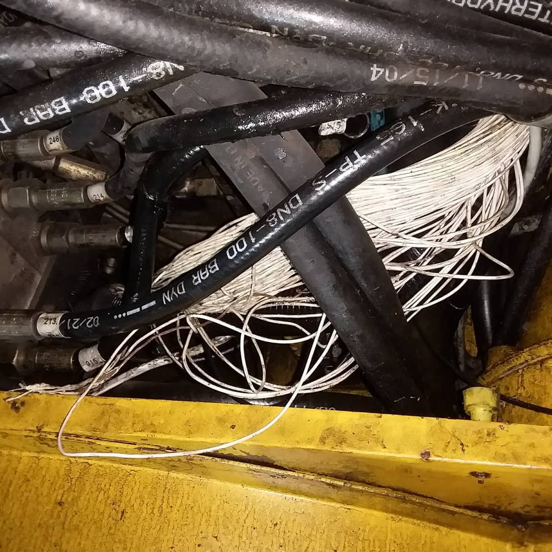
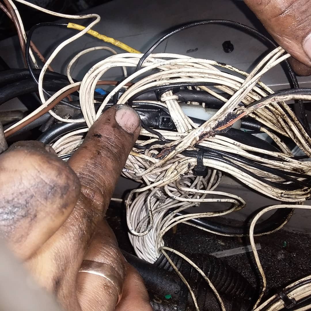
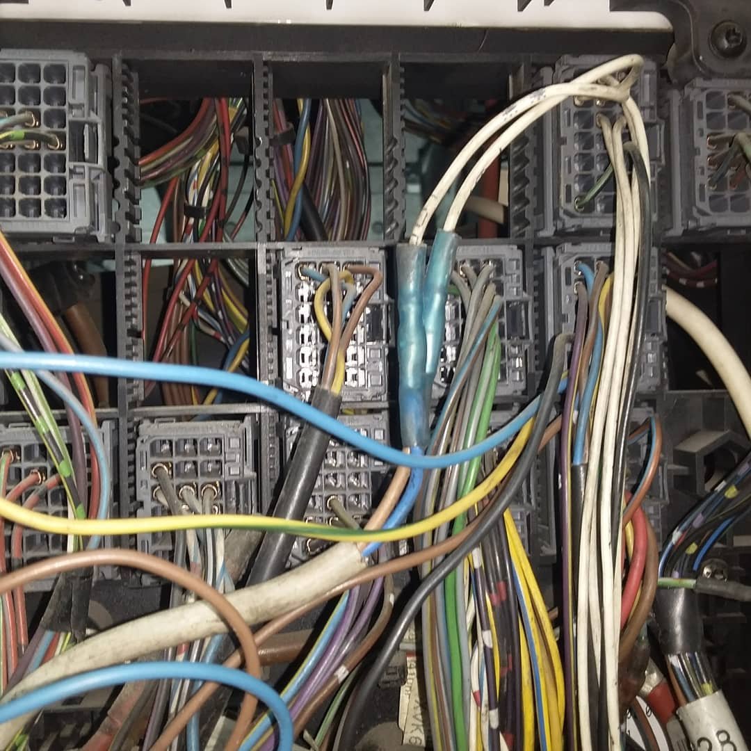
Once the control unit was restored and the machine was brought back to life, we turned our attention to the lighting system. This required opening multiple wiring harnesses and repairing the electrical circuits — a task that took two full days to complete.
-
- Close-up view of wiring harness in an O&K excavator
-
- Repairing the wiring harness in an O&K excavator
-
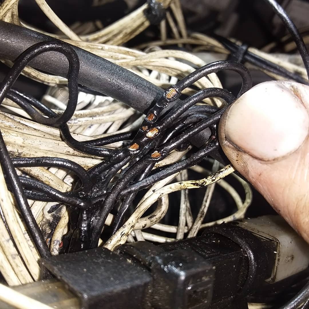
- Close-up of damaged wiring harness discovered during diagnostics on an O&K excavator
-
- Close-up of damaged wiring harness on an O&K excavator.
Its functions are gradually being restored. Only one task remains — to revive the compressed-air supply to one of the consumers.
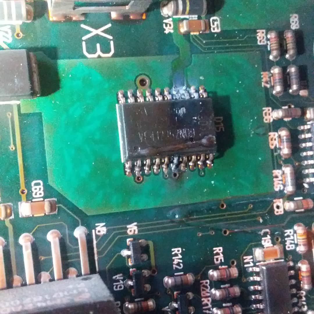
And later, after another inspection, we found something else — broken speed sensor.
-
- Repairing the ECU circuit board of an O&K excavator after detecting burned microchips
-
- Broken speed sensor on an O&K excavator discovered during diagnostics
-
- O&K excavator undergoing electronic diagnostics and control-unit repair with USB Autoscope IV
The USB Autoscope IV is an excellent diagnostic tool that we use whenever it is necessary to capture and analyze signals from:
- sensors
- CAN data buses
- actuators
- microprocessors
- control modules
- and many other electronic components
In heavy equipment diagnostics, reliable signal visualization is crucial — and Autoscope provides that with precision and convenience.
Once again, I want to thank the creators and developers of this tool and the software we use daily. Their work makes complex diagnostics possible, even on heavy machinery like this O&K excavator.
2. Diagnostics of 2012 Iveco Stralis heavy-duty truck
Machines are very much like people — as they grow older, their “health” begins to fail. Recently, we were visited by a truck whose electrical system was clearly not feeling well. A closer inspection revealed that the problem had brought the vehicle dangerously close to a point where only a full wiring replacement or major overhaul would help.
Today we want to share a case that we believe deserves special attention.
The patient: a 2012 Iveco Stralis equipped with a Cursor 10 engine.
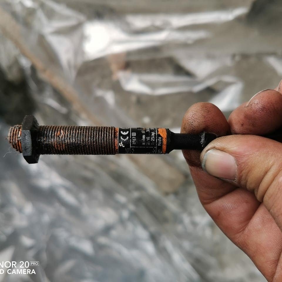
The complaint: an error code from the crankshaft position sensor and difficulty starting the engine.

Before the truck came to us, the driver had already replaced the crankshaft position sensor — the very sensor the ECU had been intermittently complaining about. Our multibrand diagnostic system confirmed the presence of the error.
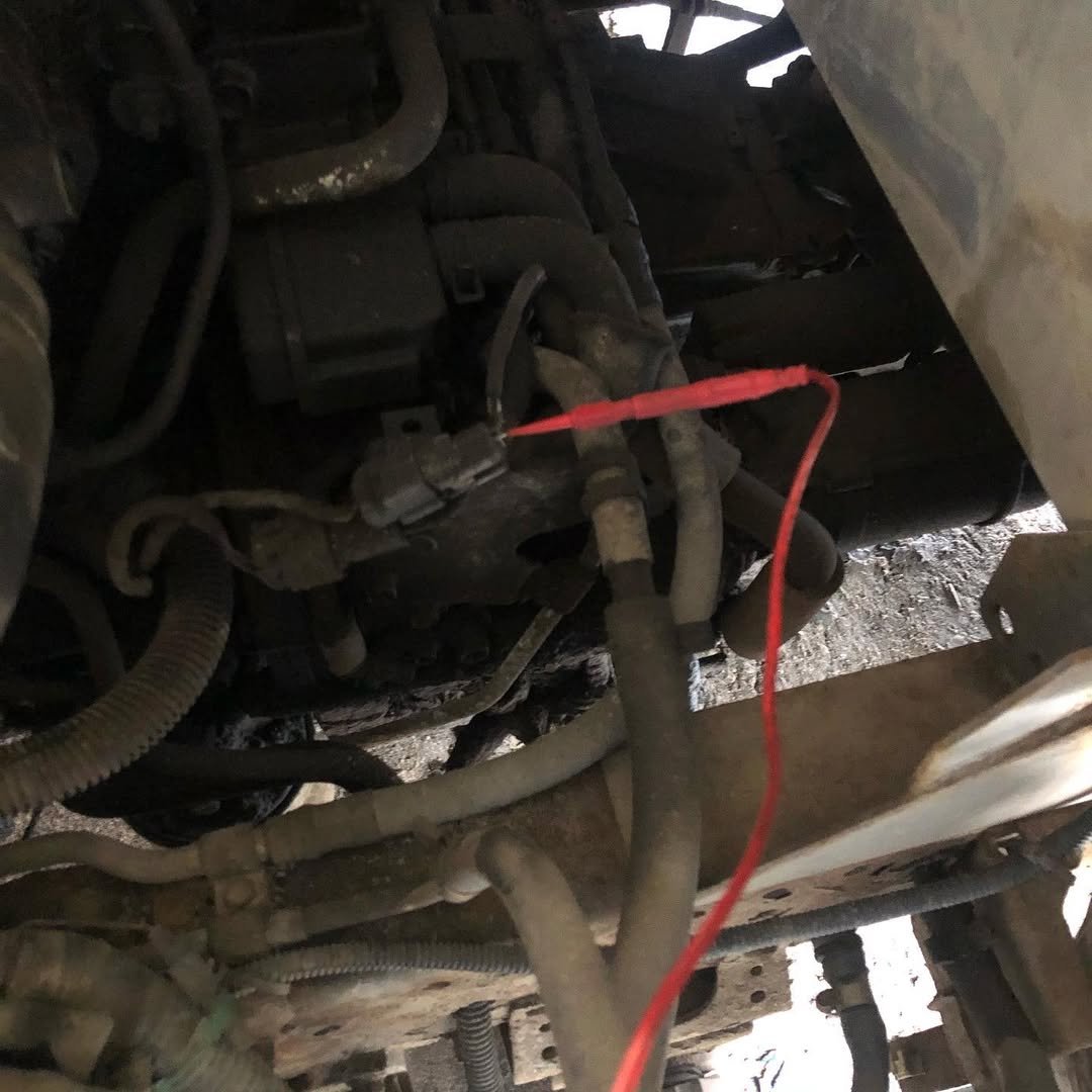
Naturally, we began by inspecting the wiring. Sure enough, we found a chafed wire. Problem solved? Unfortunately, no — the error remained.
While we were restoring the wiring and checking the connector on the control unit, the owner brought another ECU and insisted we try it. We connected it, but there were still no changes. At this point it was becoming increasingly clear that the issue was inside the engine itself, not the electronics.
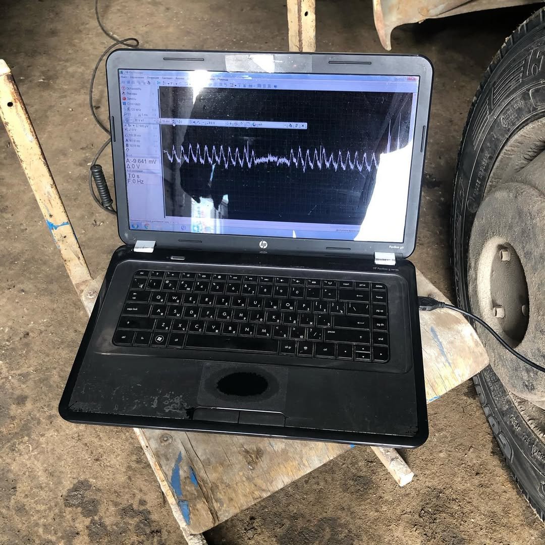
Oscilloscope to the Rescue
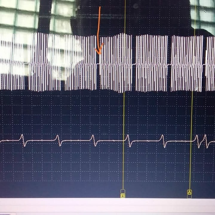
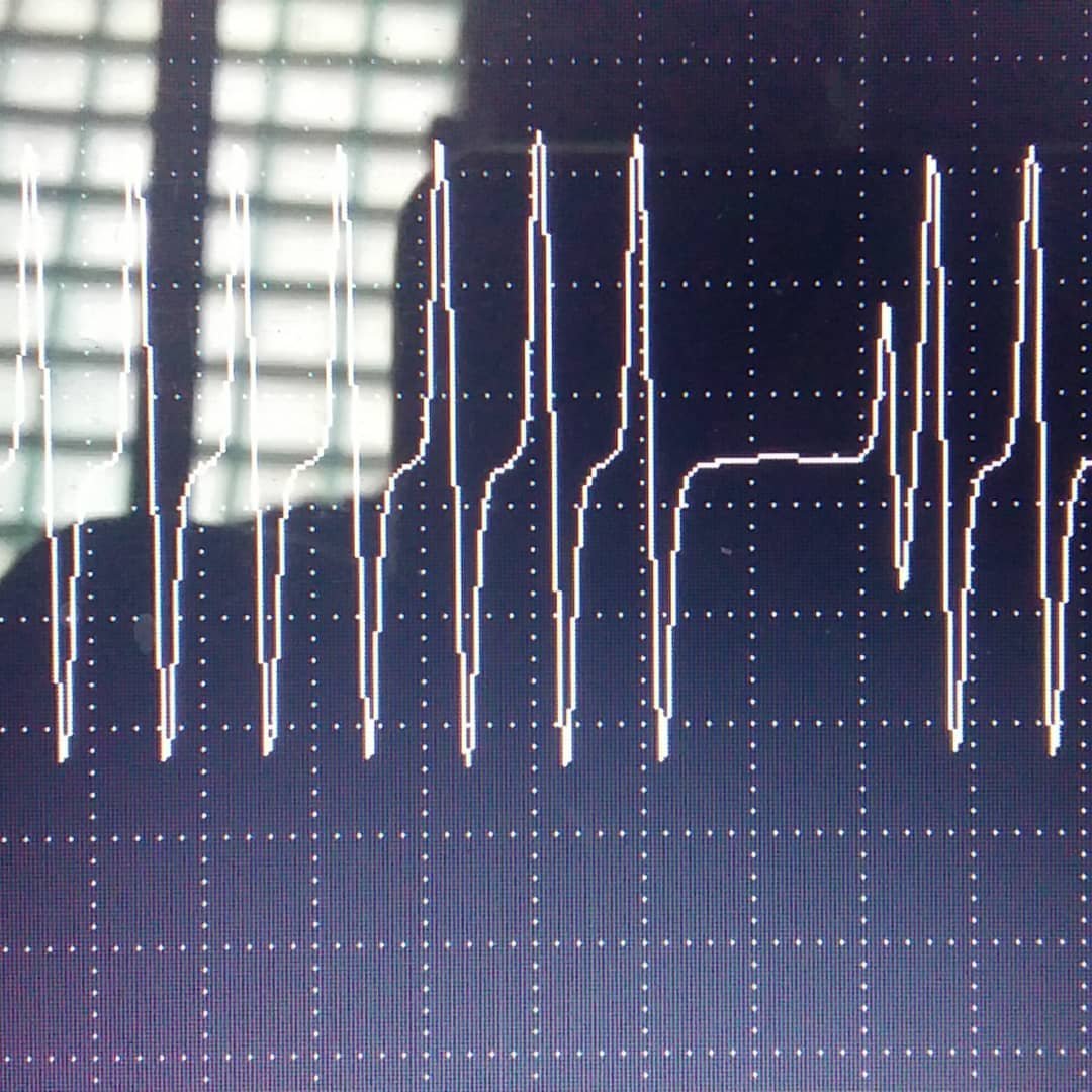
We connected the oscilloscope and immediately noticed a small but suspicious anomaly in the crankshaft sensor signal. The disturbance was highlighted with an arrow in the photo and zoomed in another image.
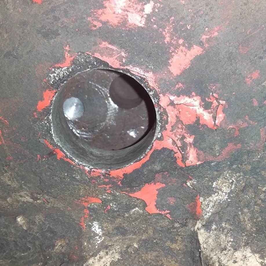
The investigation revealed the unexpected truth:
When the driver replaced the original sensor, he broke the old one and tried to extract the remains using a drill—accidentally hitting the flywheel in the process. The damage was clearly visible in the image.
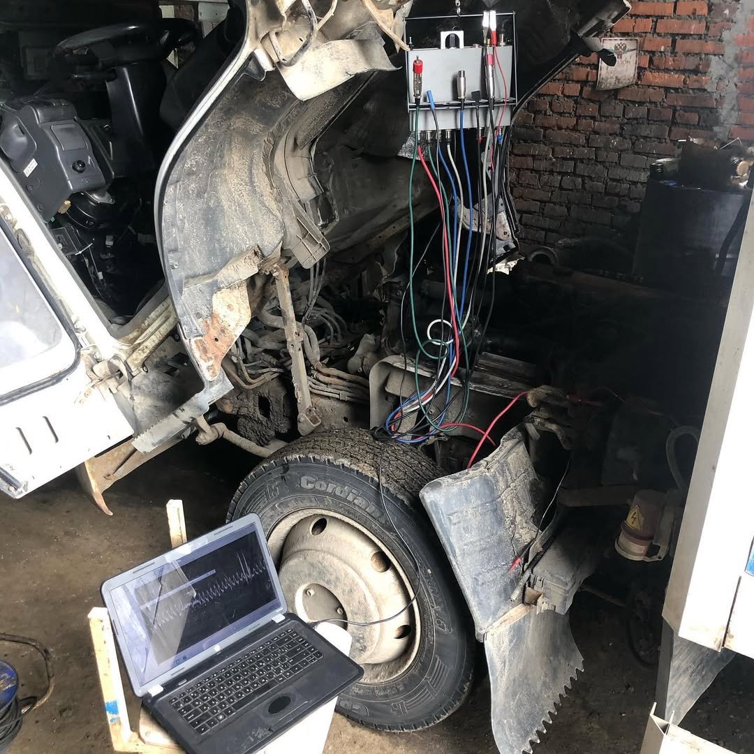
-

- Iveco Stralis 2012 showing failed crankshaft position sensor and waveform analysis with USB Autoscope IV
-
- Iveco Stralis 2012 showing failed crankshaft position sensor and waveform analysis with USB Autoscope IV
-

- Damaged flywheel
The irony is that the original problem — the intermittent error — was simply caused by a single worn-through wire. A repair that costs next to nothing.
But the situation could have escalated dramatically. The owner was on the verge of buying a new ECU, a new sensor, and potentially more components — easily exceeding significant money in unnecessary expenses.
This case is a good reminder that proper diagnostics and careful handling during repairs are crucial — for both people and machines.
3. Isuzu NQR truck
The owner complained that the truck was unable to deliver the required power, especially when driving under load. There were no obvious mechanical failures, and standard diagnostic tools did not reveal any active fault codes. Yet the engine simply would not produce full output.
Because of the vague symptoms and the absence of clear ECU errors, this case required a deeper, signal-level analysis.
-
- Diagnostics in progress on an Isuzu NQR truck using the USB Autoscope IV oscilloscope
-
- Connecting diagnostic equipment to an Isuzu NQR truck
-
- Waveform on an Isuzu NQR truck measured with the USB Autoscope IV oscilloscope
-
- Isuzu NQR undergoing diagnostics using the USB Autoscope IV vehicle oscilloscope.
Very quickly, the Autoscope revealed what ordinary diagnostics could not:
The crankshaft timing marks are incorrect.
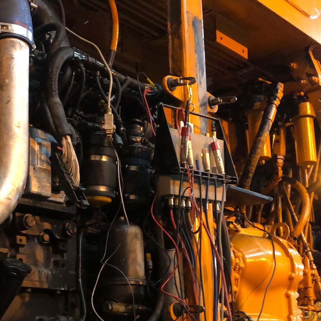
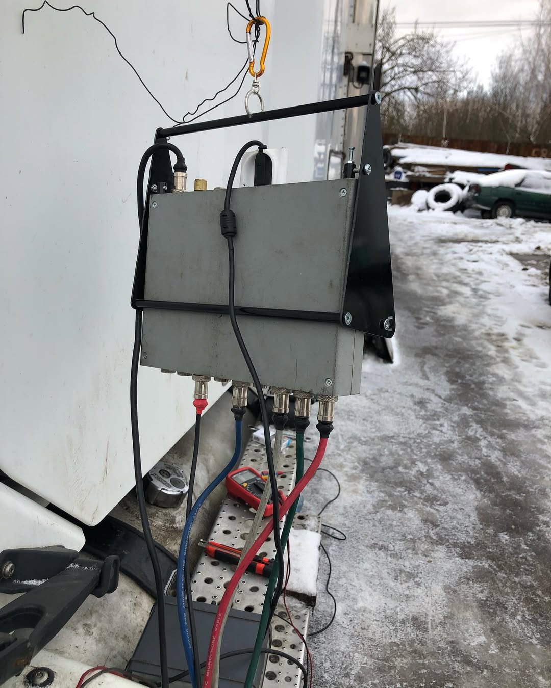
4. Diagnosing fuel system failures on Kalmar CSC340 straddle carriers
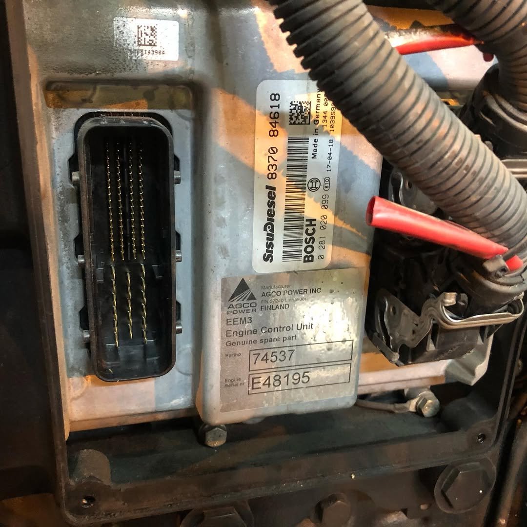
A case study on two CSC units powered by SISU engines
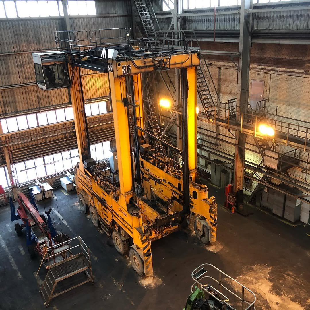
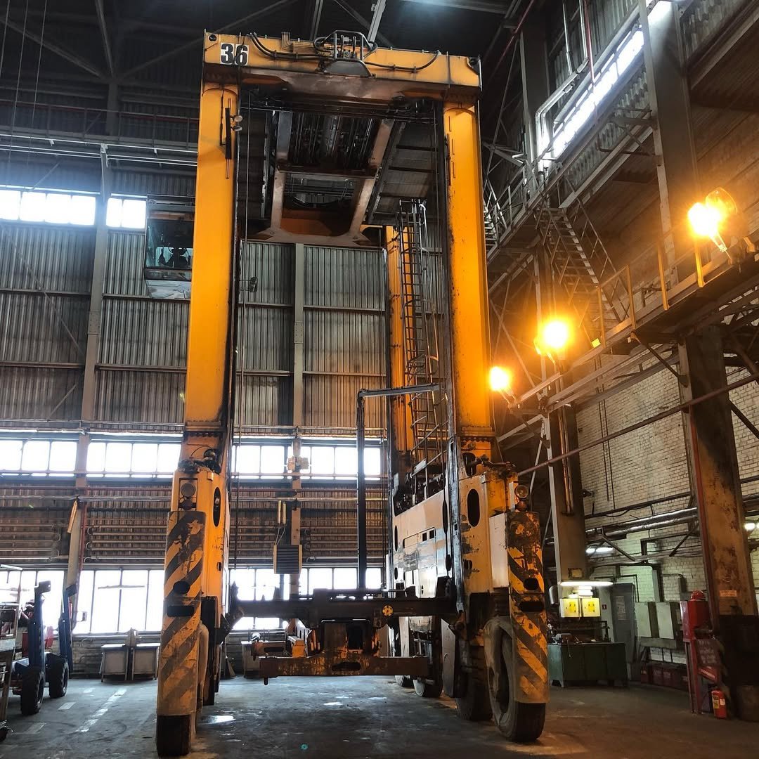
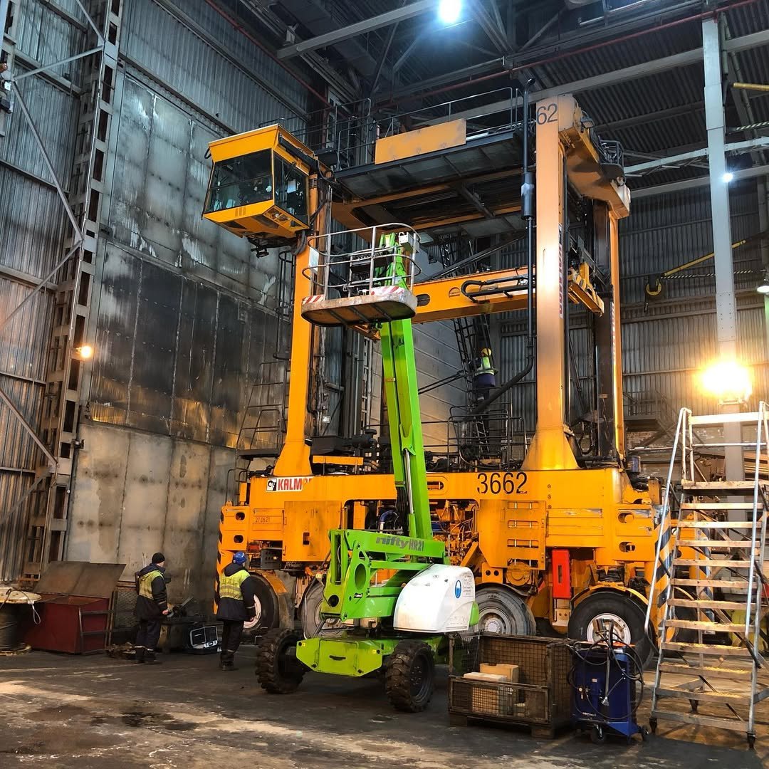
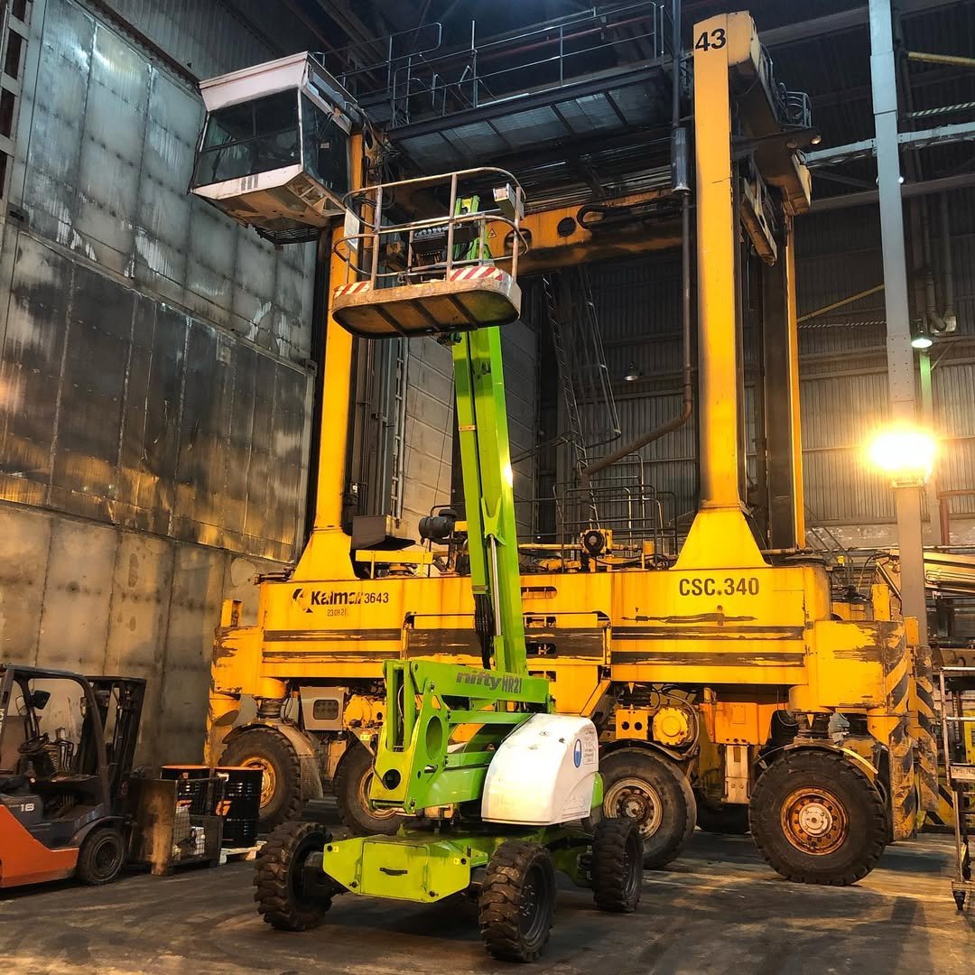
Straddle carriers like the Kalmar CSC340 are the giants of container terminals. Designed to lift, transport, and stack heavy containers with precision, they rely on powerful and synchronized twin-engine systems. When one engine fails, the entire machine loses efficiency—and sometimes becomes completely unusable.
Recently, our team was called to diagnose two Kalmar CSC straddle carriers, each experiencing serious issues with one of their two SISU 6-cylinder engines. The symptoms were similar but not identical, and both machines were operating at reduced performance.
-
- Straddle carrier loading containers at a terminal—equipment targeted for diagnostics
-
- Straddle carrier
Machine 1
- Engine ran with significantly reduced power
- Fuel pressure errors
- Engine stalled when idling
- Unstable running at low RPM
- Fuel pressure errors
- Noticeable fuel pressure pulsation
- Floating idle speed
- Power limitation after start
- Engine dropped to 1200 RPM and switched to limp mode
In both cases, the "healthy" engine was forced to carry the full workload of the straddle carrier, creating a high-risk operating condition.
The onboard self-diagnostic system gave only generic error messages—no details, no causes, and no direction. The AGCO diagnostic system (SISU Engine 74CT) also failed to provide clear answers.
As has become our golden rule:
When everything is unclear, we bring out the USB Autoscope IV.
This tool has saved us countless hours—and this case was no exception.
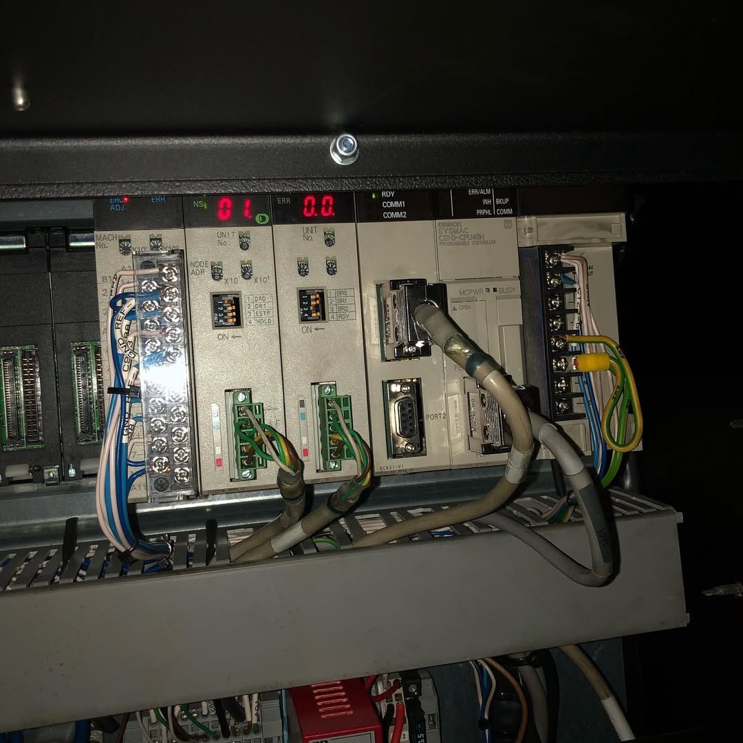
Step 1: Checking the CAN bus
Within minutes the Autoscope confirmed that the CAN network was healthy. No communication noise, no interruptions.
Step 2: Analyzing sensor signals
All sensors appeared normal. No obvious electrical faults.
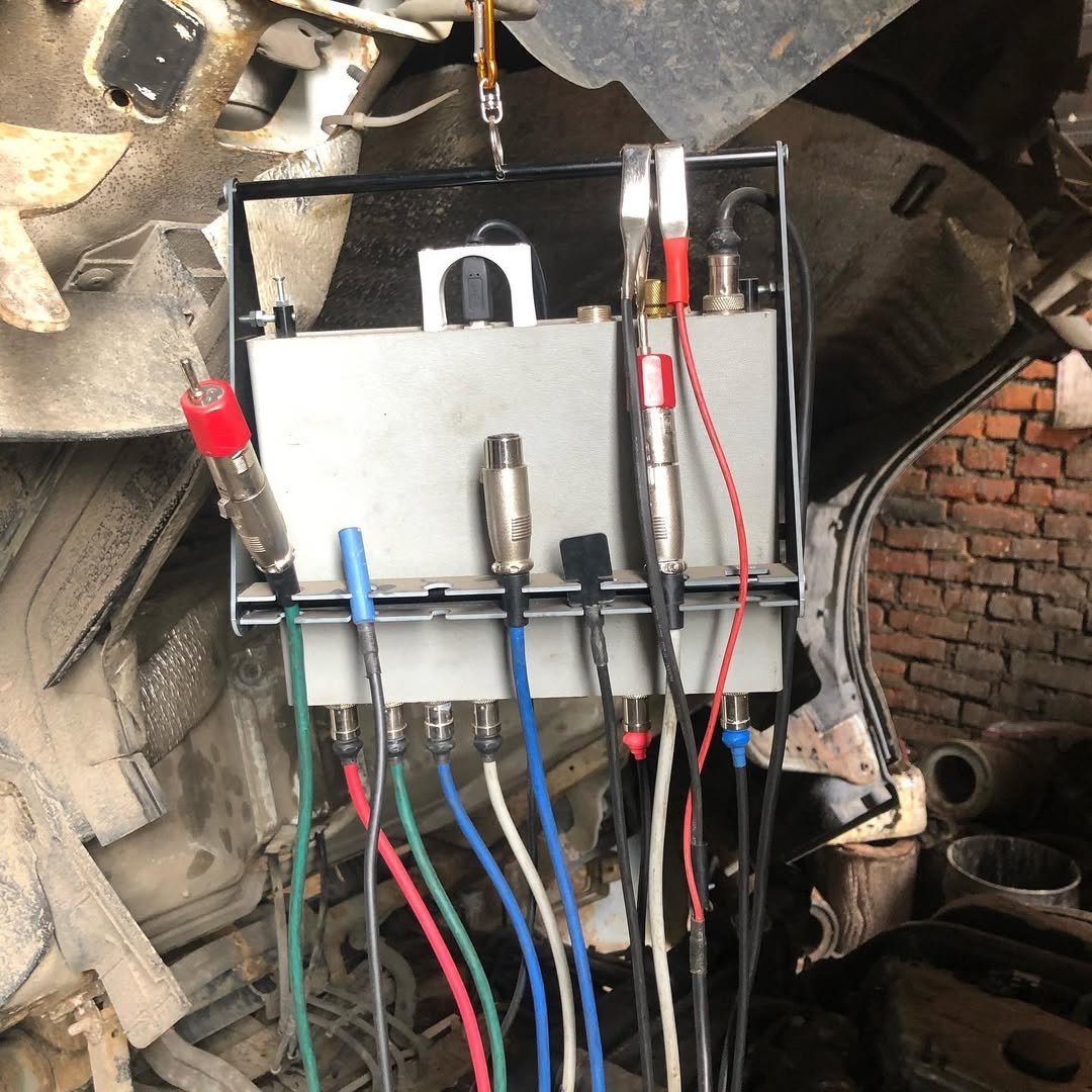
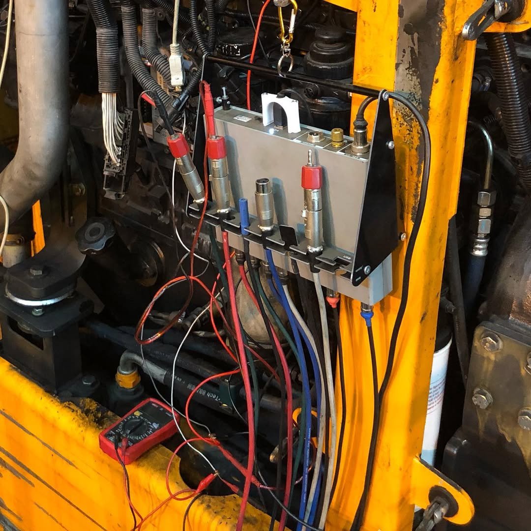
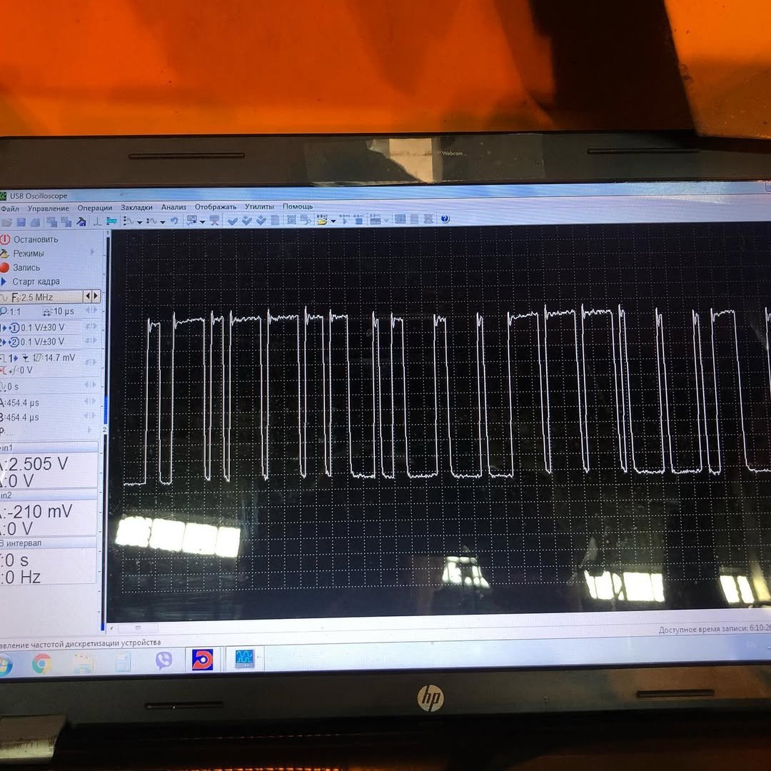
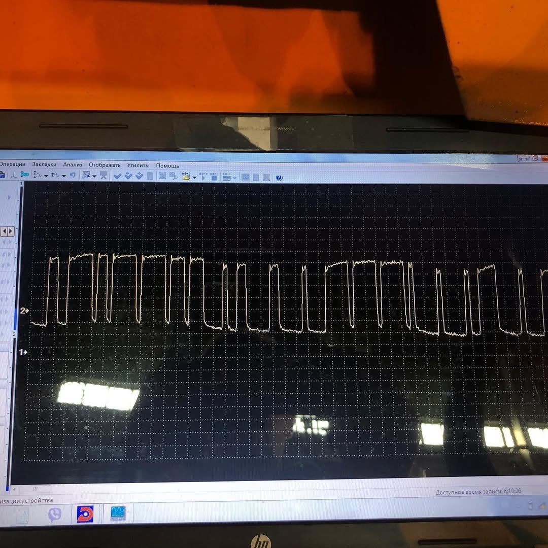
Step 3: Fuel pressure signal test
Diagnostics showed a fuel-rail pressure problem in the first machine, and in the second one — fuel-filter pressure errors, pressure pulsation, and unstable idle speed. In both cases the engines were limiting power, and the first engine would stall while idling.
We connected the USB Autoscope IV oscilloscope to the first power unit to check the fuel-pressure sensor. At idle, the signal was missing or dropping out. Replacing the sensor resolved the issue.
The second engine had a problem with the fuel filter — it had very poor flow capacity. Replacing the filter solved the problem.
-
- Fuel-rail pressure pulsation waveform on a Kalmar CSC340 straddle carrier captured using the USB Autoscope IV
-
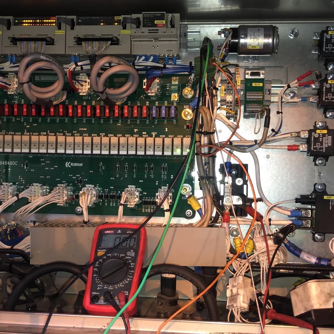
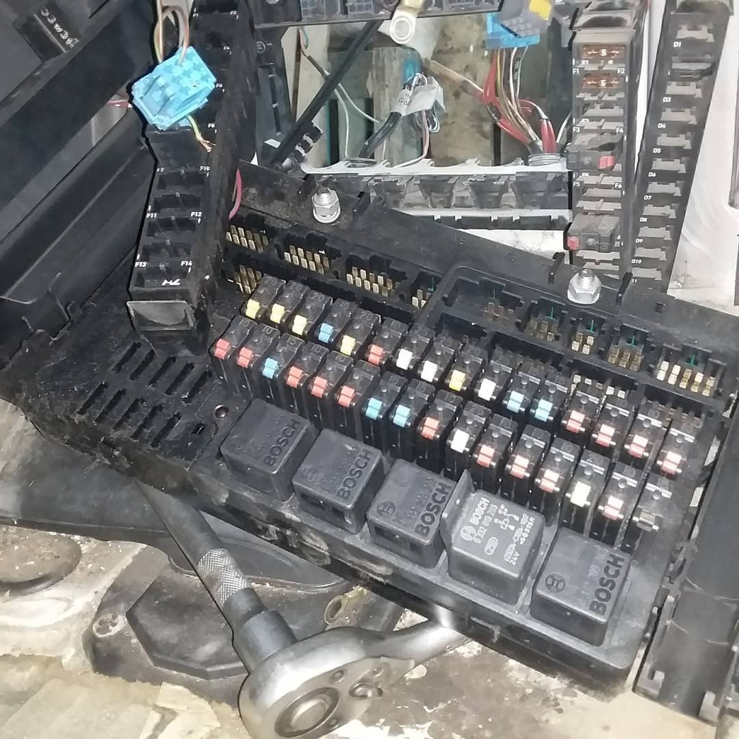
- Electronic control panel of a Kalmar CSC340 straddle carrier undergoing diagnostics
-
- Kalmar CSC340 straddle carrier
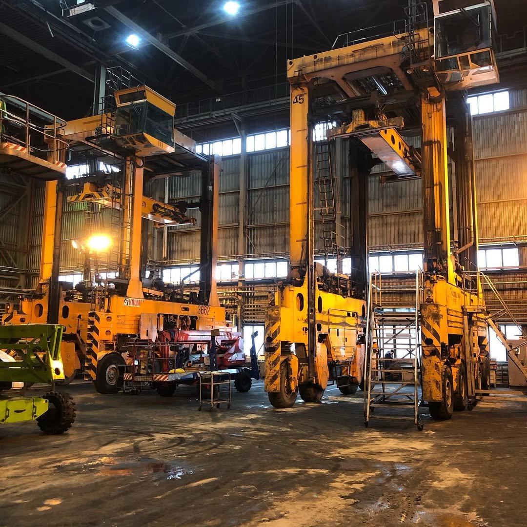
-
- Kalmar CSC340 straddle carrier in action at a container terminal yard.
Conclusion
The Kalmar CSC340 is a powerful workhorse, but like all sophisticated machinery, its performance depends on the flawless operation of its twin SISU engines.
This case demonstrates the importance of:
- Signal-level diagnostics
- Understanding engine behavior beyond ECU codes
- Using advanced tools like the USB Autoscope IV
- Not jumping to conclusions before confirming real data
A simple sensor failure and a clogged filter—one caused by a tiny wooden splinter—could have led to costly repairs, unnecessary component replacements, and extended machine downtime.
Thanks to precise diagnostics, both straddle carriers returned to service quickly and efficiently.
5. Volvo FH13 long-haul truck
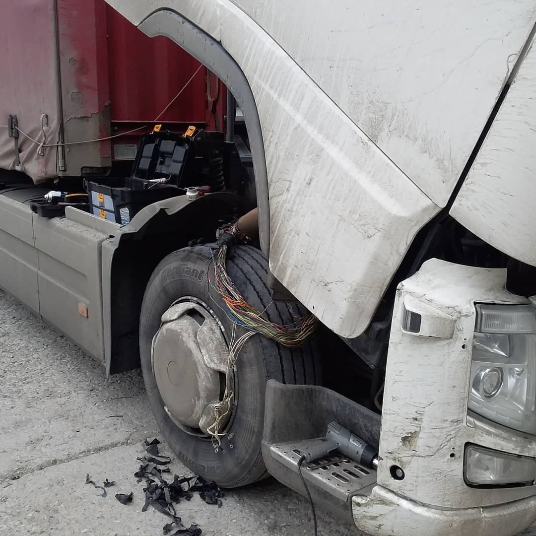
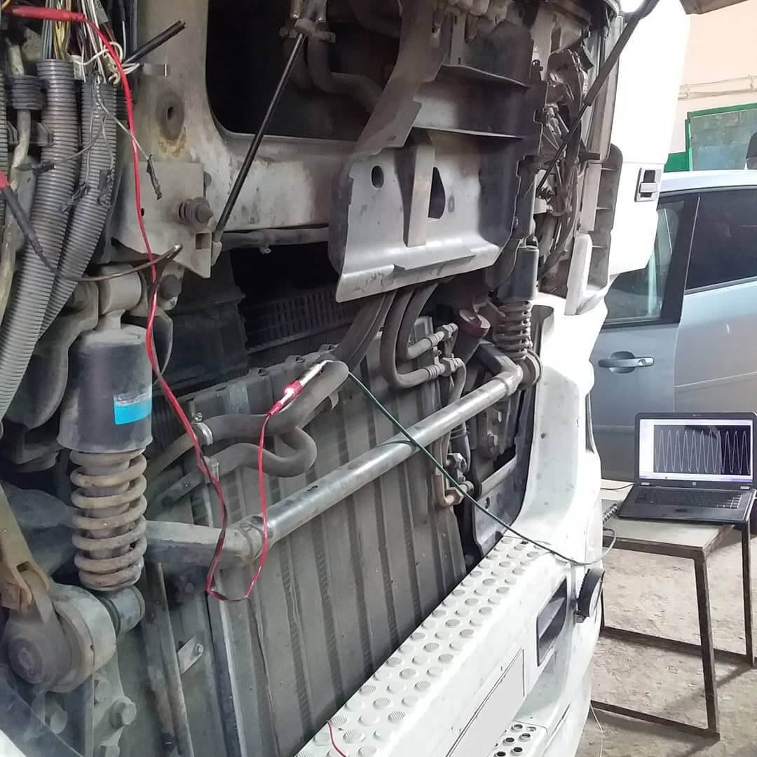
Long-haul trucks like the Volvo FH13 operate under harsh conditions, and even small electrical issues can lead to unexpected failures on the road. Recently, we were called to investigate a case where the suspension control system suddenly stopped working during a trip — a situation that can quickly become critical for vehicle stability and driver safety.
This case perfectly demonstrates the importance of thorough diagnostics, proper wiring inspection, and the effectiveness of signal-level analysis using the USB Autoscope IV.
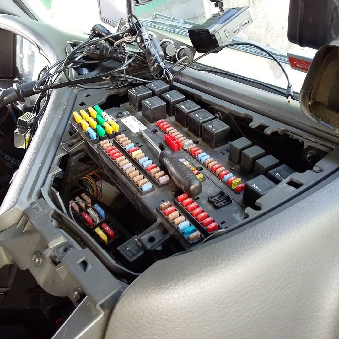
A Blown Fuse and No Diagnostic Errors
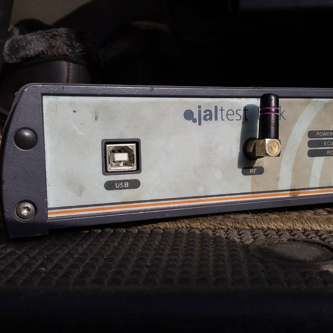
The driver reported that the suspension system had failed, accompanied by a burnt fuse. Using a Jaltest diagnostic tool, we scanned the vehicle — but no fault codes were found.
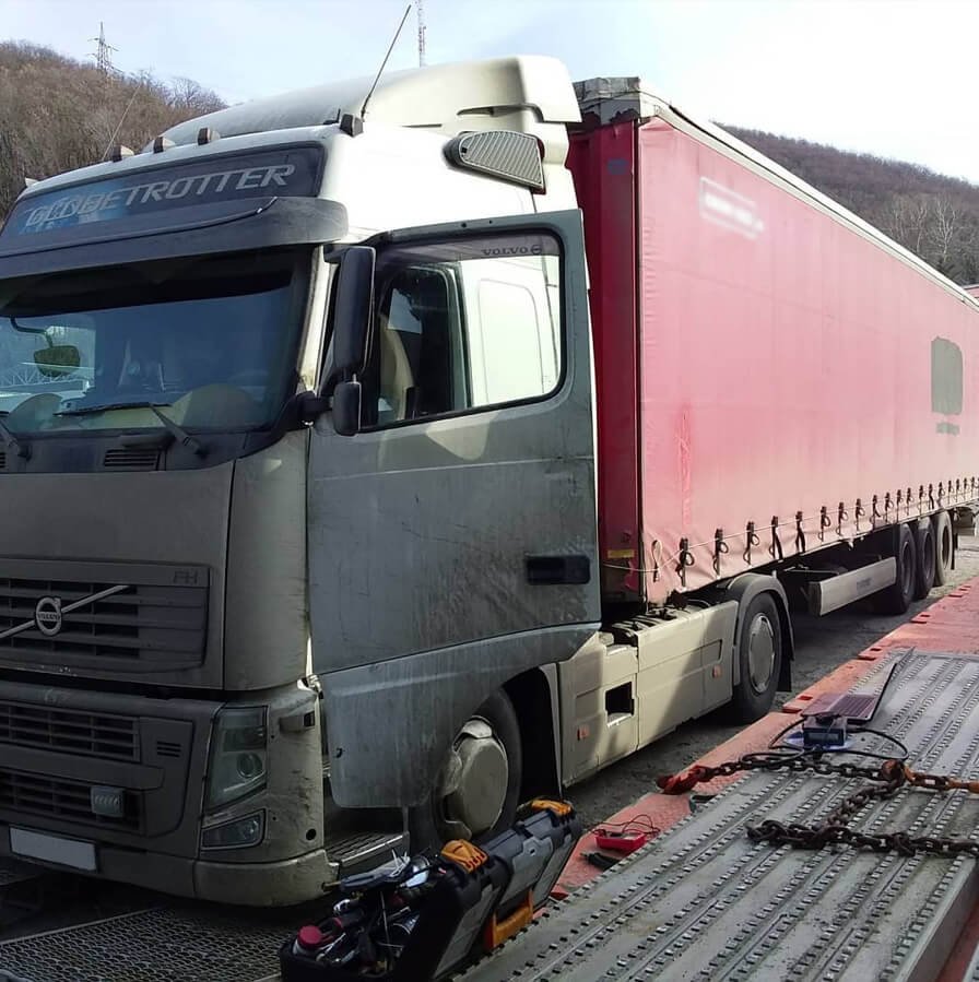
-
- Volvo FH13 heavy-duty truck undergoing diagnostics with Jaltest scanner tool
According to the driver, the system temporarily came back to life after he disconnected the ride-height sensor.
We tried repeating this: disconnecting and reconnecting the sensor — no response.
This meant the problem was deeper and not related to the sensor itself.
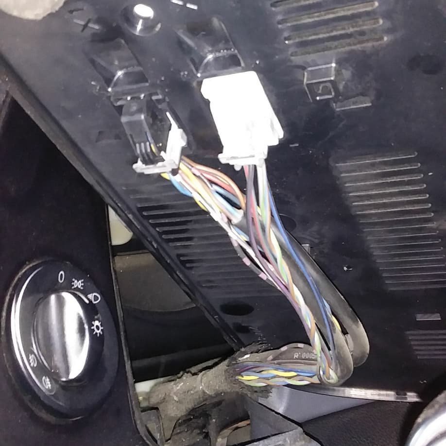
We lifted the cab to examine the wiring harness. The fault appeared to be intermittent, so a visual inspection alone wasn’t enough.
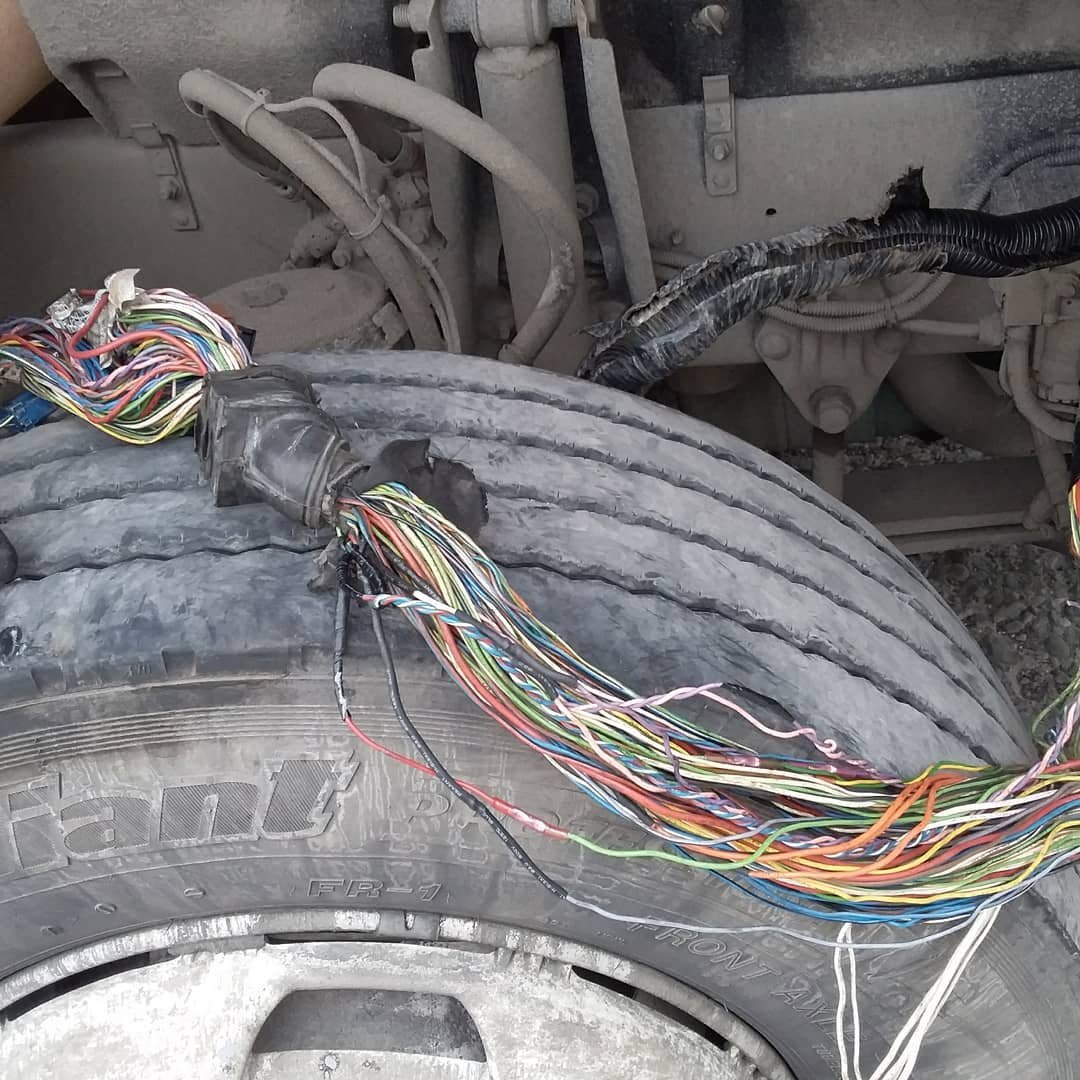
We opened the harness running from the cab and quickly found the first major clue:
Six wires had serious damage.
We repaired each damaged conductor, lowered the cab… and suddenly the control unit stopped responding again.
However, the fuse (temporarily replaced by an incandescent test lamp) remained intact. This told us the short circuit had been eliminated — but the control unit still wasn't getting the power it needed.
Using a multimeter, we verified:
- Power supply — OK
- Ground — OK
This suggested the problem was not in the main supply lines.
We connected the USB Autoscope IV to read the CAN bus and power-related signals.
Everything looked perfect:
- CAN-High and CAN-Low were symmetrical
- No noise
- No missing frames
- Signal shape correct
The CAN bus was operating exactly as it should.
This eliminated an entire category of potential faults.
-
- Technician repairing the cabin wiring harness of a Volvo FH13 heavy-duty truck
-
- Technician inspecting and repairing the wiring harness on a Volvo FH13 heavy-duty truck
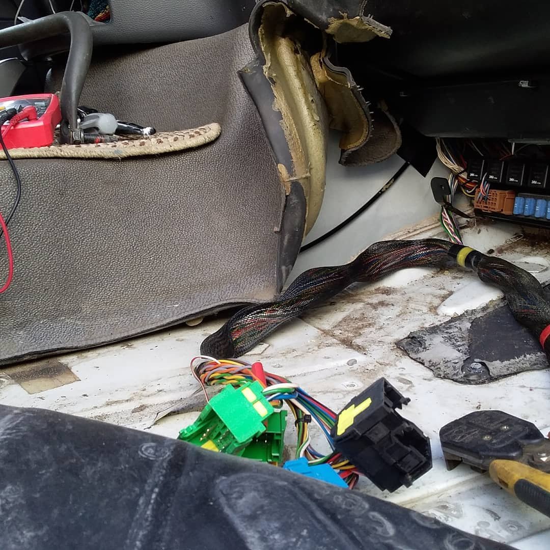
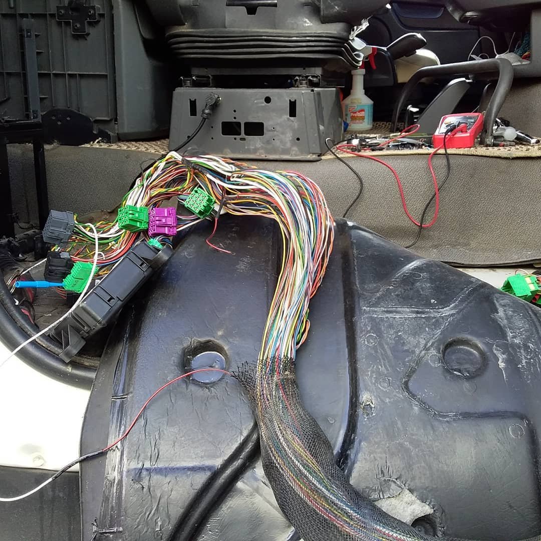
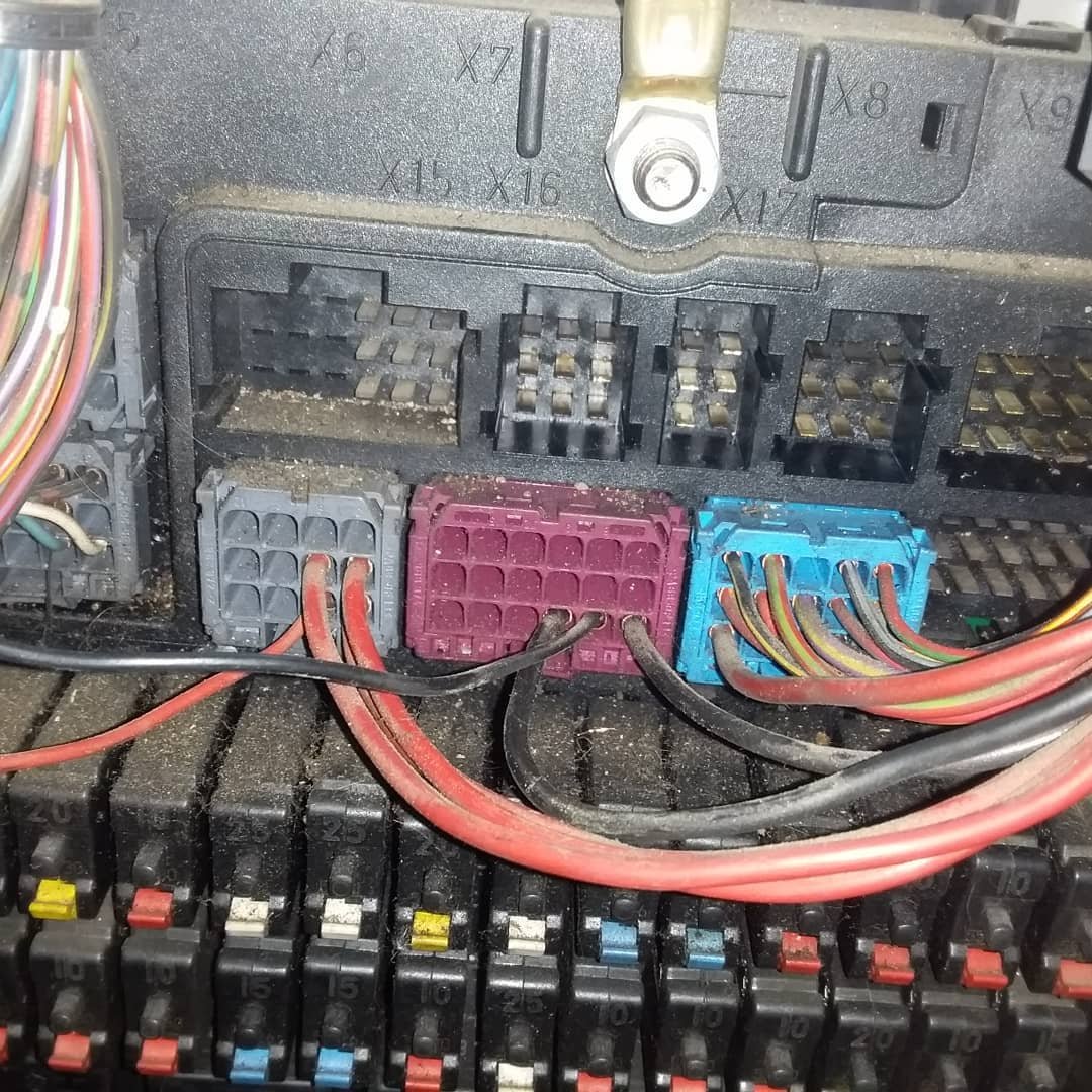
We moved deeper, we removed the passenger seat, opened the wiring channels, and released the harness going into the tool compartment behind the seat.
We disconnected the harness and tested each conductor under load. And that’s when we found it:
A partially burned power wire hidden under the cabin partition panel.
The damaged section was covered by a protective sleeve (“stocking”), making it invisible during normal inspection.
This explained the intermittent behavior: sometimes the wire made contact, sometimes it didn’t.
We repaired the damaged wire, restored insulation, secured the harness, and reconnected everything.
The suspension control system came back to life.
As a final step, we:
- checked all system fault codes
- performed a clutch calibration
6. Mercedes-Benz Actros 460 heavy-duty truck
Heavy-duty trucks like the Mercedes-Benz Actros 460 are known for their reliability and advanced electronic systems. However, when several of these systems fail at once, diagnosing the root cause becomes a real challenge. Recently, we worked on an Actros 460 with an automatic transmission that suffered from multiple electrical and communication issues. This case demonstrates how deeply intertwined modern truck electronics have become—and how proper diagnostics can save a vehicle from extensive downtime.
The vehicle arrived with several troubling symptoms:
- failure to display the current transmission gear
- the truck occasionally refused to respond to gear-shift commands
- the selector switch module behaved erratically
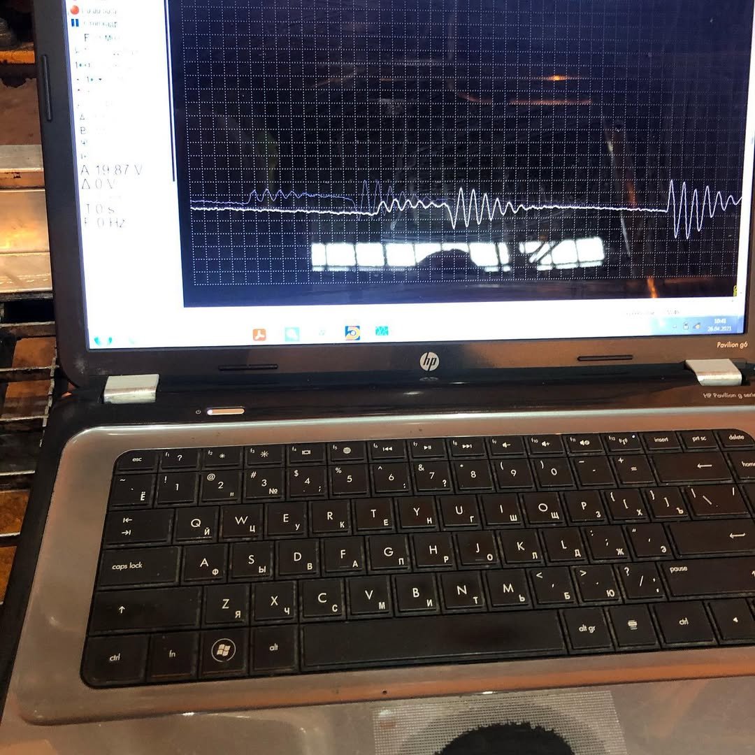
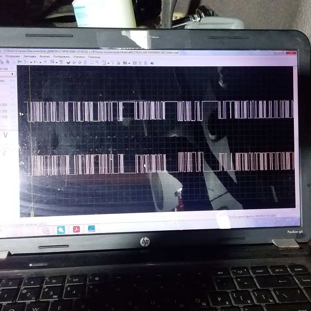
- the transmission control unit produced unreadable oscilloscope waveform

-
- Distorted CAN-bus waveform on a Mercedes-Benz Actros 460 heavy-duty truck measured with the USB Autoscope IV oscilloscope
-
- Mercedes-Benz Actros 460 undergoing diagnostics using USB Autoscope IV
-
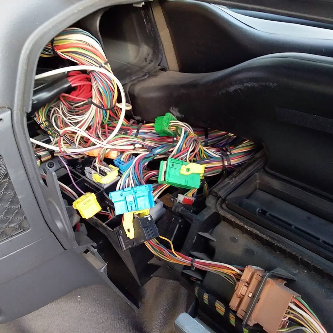
- MB Actros 460 wiring connectors
The Transmission Control Module (TCU) was removed and examined on the bench. The suspicious waveform indicated a serious internal failure.
The culprit was identified as a faulty CAN controller inside the module.
Even after repairing the TCU, the vehicle’s electronic behavior remained inconsistent. Communication with several ECU modules was unstable, and some data exchange simply didn’t occur.
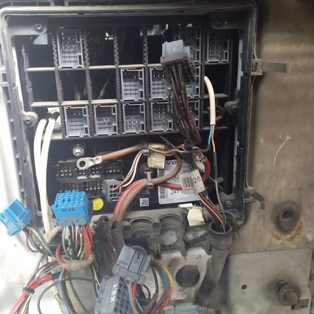
Further investigation pointed to the ZBR (Zentraler BordRechner) — the central body controller responsible for managing and routing much of the truck’s internal communication.
Our electronics specialist discovered:
- The ZBR’s internal memory was completely full
- Important data from several ECUs was missing or corrupted
- The ZBR could not exchange information with other modules reliably
To proceed, the ZBR needed to be physically removed from the Actros.
Our electronics specialist requested its removal, and the module was carefully extracted and brought “to the table” for inspection and repair.
-
- Mercedes ZBR central body controller module diagnostics
ZBR unit is responsible for powering all other modules, controls the lights, windshield wipers, washers and, most importantly, stores information from all other units. This repair story highlights an important principle in modern truck diagnostics:
A failure in one module can cascade into multiple symptoms across the entire vehicle.
Thanks to methodical troubleshooting and proper electronic repair techniques, the Actros is now back on the road—with a transmission that shifts correctly and an electronic system that communicates the way it should.
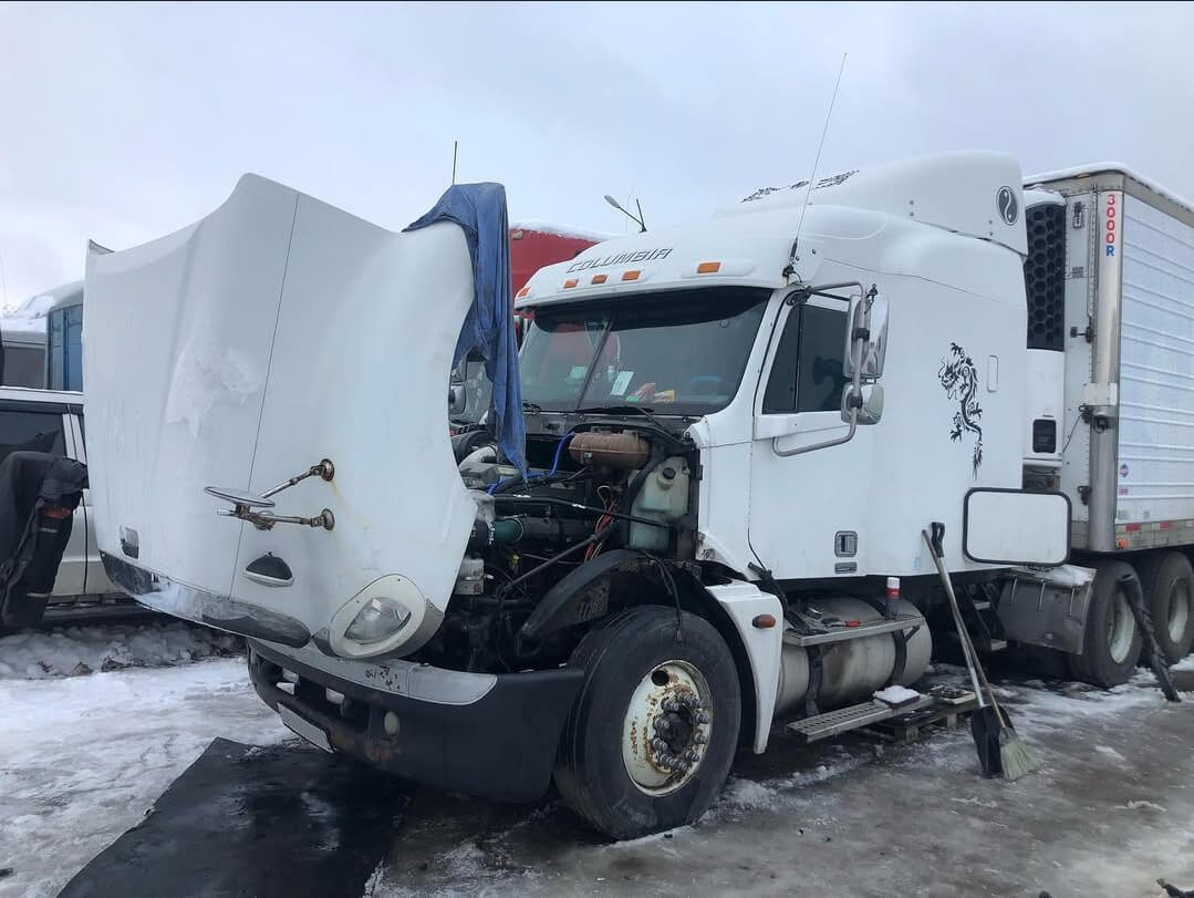
8. Freightliner Columbia 112/120 heavy-duty semi-truck
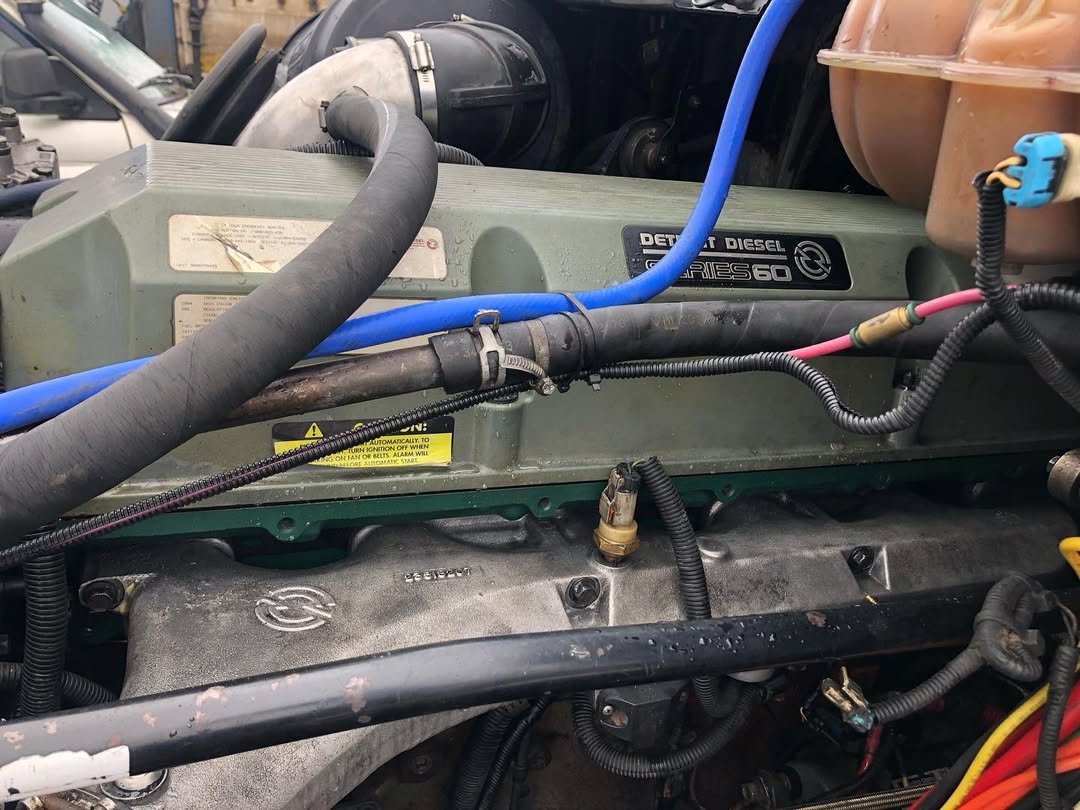
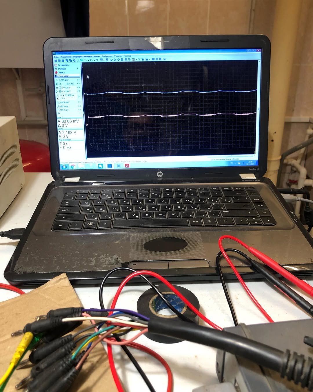
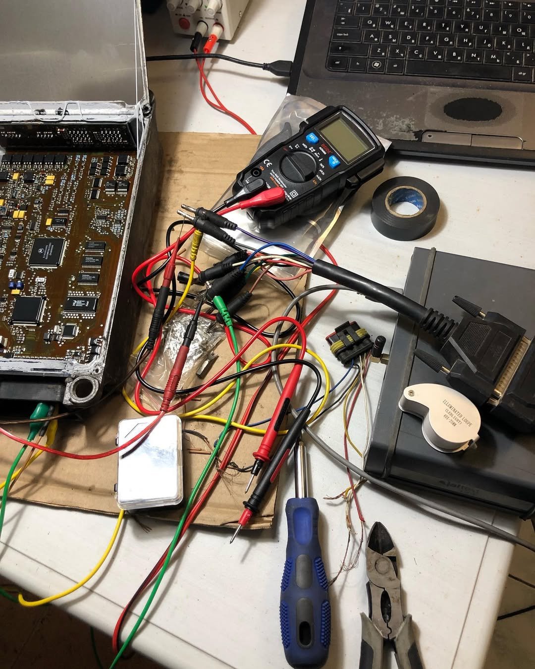
The Freightliner Columbia equipped with the legendary Detroit Series 60 diesel engine is a true workhorse of North American trucking. Simple, powerful, and dependable—yet even these trucks can present complex challenges when major engine components are replaced. Recently, we completed a repair that highlights just how critical proper wiring, module configuration, and CAN-bus diagnostics are on heavy-duty trucks.
The Beginning: Installing a New Cylinder Head (Non-EGR Version)
The truck arrived for a major repair: replacement of the cylinder head with a new non-EGR version.
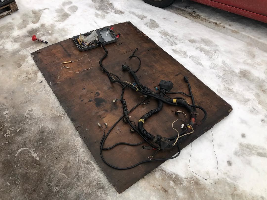
Because the EGR and non-EGR versions differ electronically, the job also required:
- installing a different ECU
- installing a different engine wiring harness
- connecting and routing all corresponding wiring changes
By the next day, we had completed the full wiring integration of the Detroit Series 60 engine. Mechanically and electrically, everything appeared correct.
-

- Freightliner Columbia undergoing Detroit Series 60 diagnostics using the USB Autoscope IV
-

- Repairing a Freightliner Columbia after diagnostics with USB Autoscope IV
-
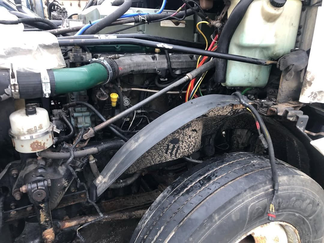
- Detroit Series 60 diesel engine
-
- Technician inspecting and repairing the wiring harness in a Freightliner Columbia heavy-duty truck
But there was a problem.
No Communication With Diagnostic Equipment. When we attempted to connect using Jaltest diagnostics, the truck refused to communicate.
No ECU response. No data. No connection to the engine electronics.
On Series 60 engines, this usually means one thing: CAN-bus failure.
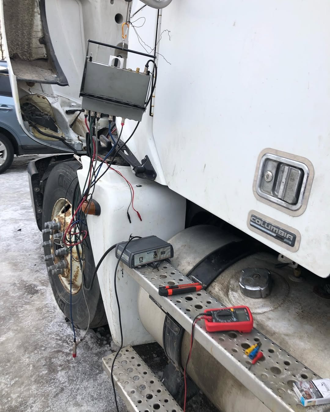
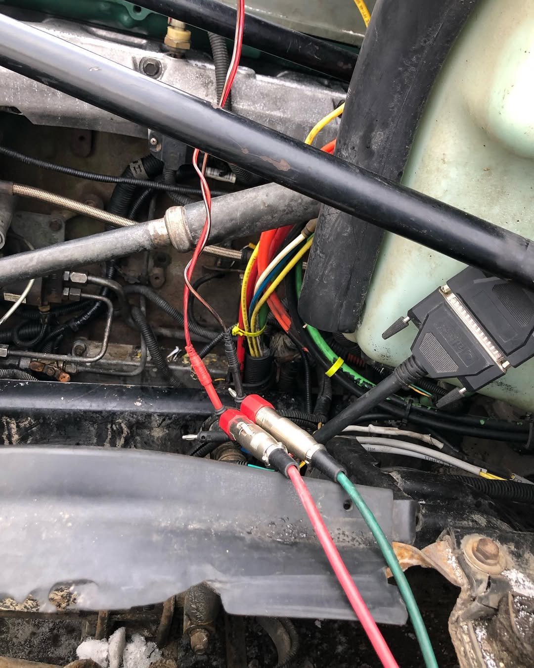
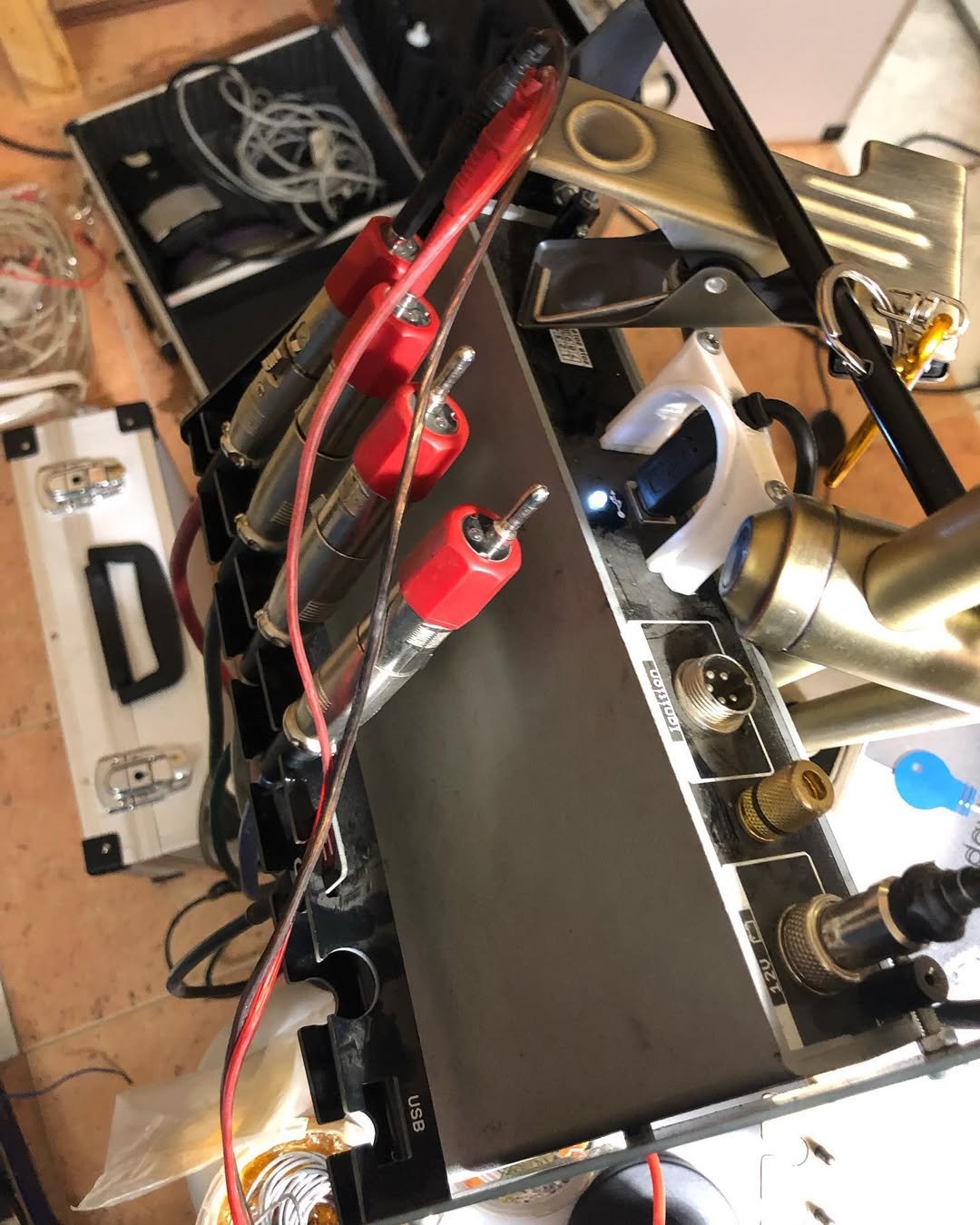
The USB Autoscope IV is our go-to tool for reading real-time electrical signals on heavy-duty networks. Connecting it to the data line revealed the issue instantly:
The CAN line was not producing a valid signal.
This confirmed that the problem was not in the new ECU or the new harness, but somewhere upstream. We removed the ECU and took it “to the bench” for standalone testing.
-

- Freightliner Columbia truck being diagnosed using the USB Autoscope IV automotive oscilloscope
-
- Connecting USB Autoscope IV to the Freightliner Columbia truck for diagnostics
-
- Faulty CAN bus waveform detected on a Detroit Series 60 ECU using USB Autoscope IV
-
- Faulty CAN-bus Detroit Series 60 ECU detected using USB Autoscope IV.
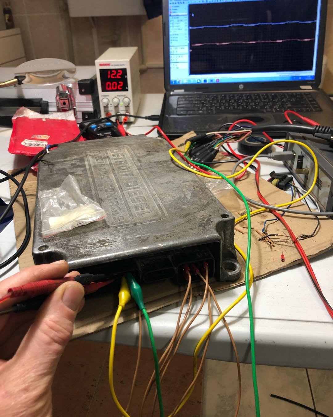
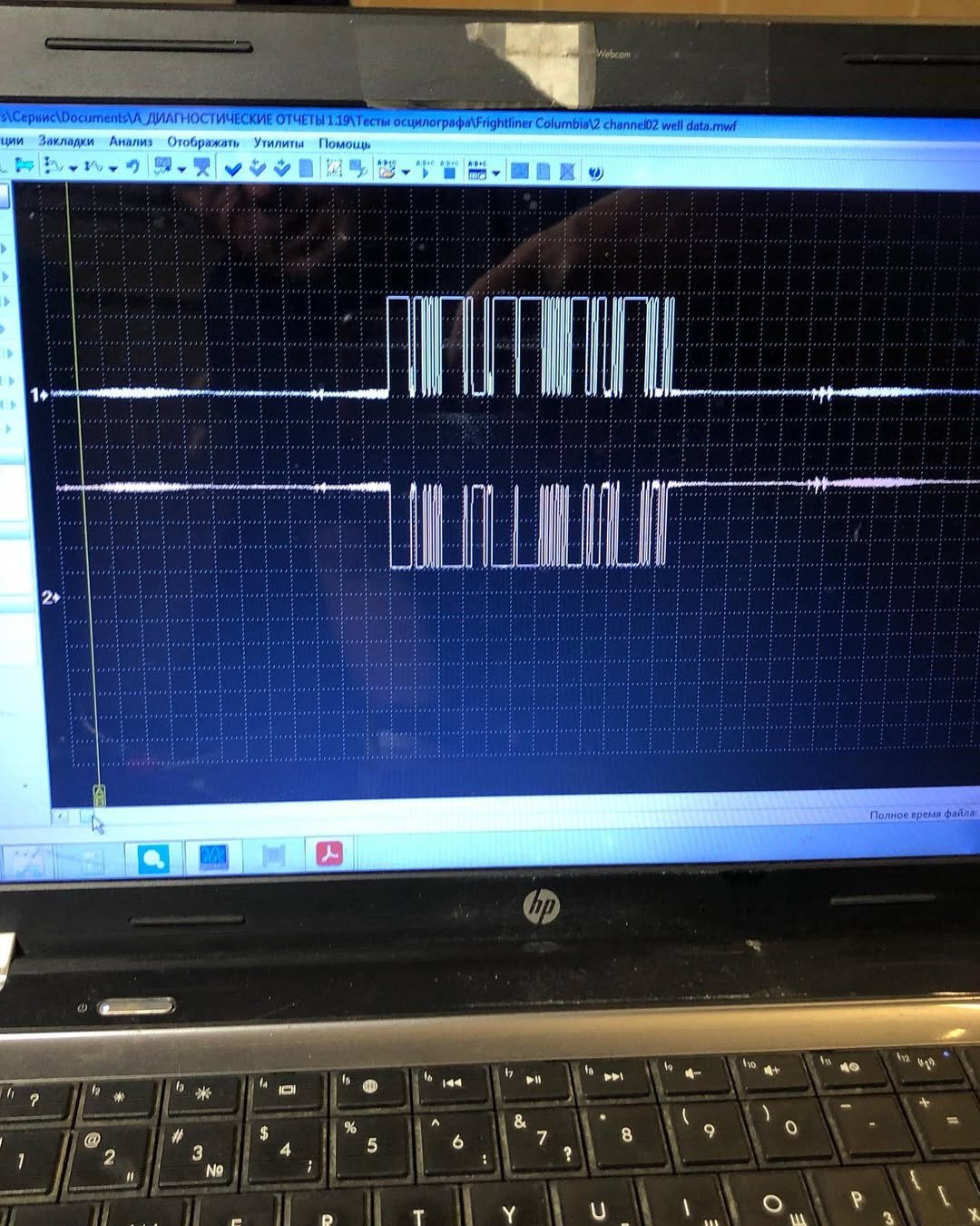
That evening, we finally managed to establish communication with the module—confirming that the ECU and the new engine harness are good.
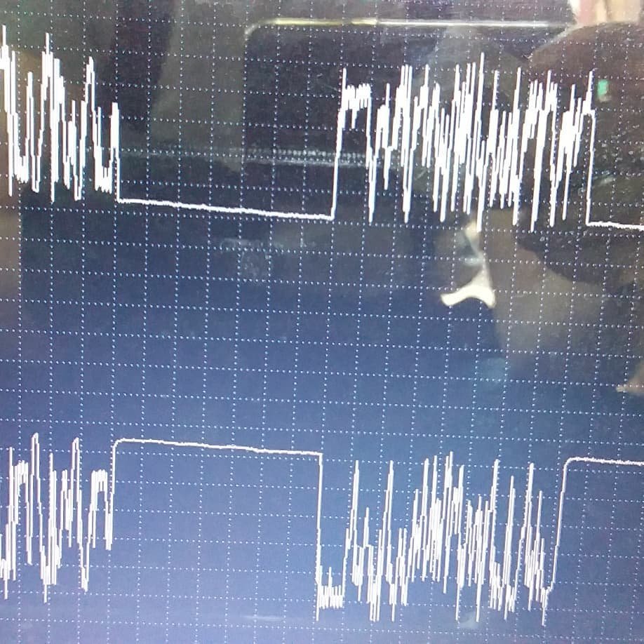
On the last photo, the oscilloscope shows a perfect CAN waveform, exactly as it should appear:
- symmetrical high and low lines
- clean edges
- correct voltage levels
- no noise or distortion
This meant the problem was not inside the ECU.
-
- Freightliner Columbia truck being diagnosed with the USB Autoscope IV oscilloscope
-
- Connecting the USB Autoscope IV oscilloscope to the Detroit Series 60 engine ECU for diagnostics
-
- The USB Autoscope IV motortester — advanced automotive oscilloscope for vehicle diagnostics
-
- Correct CAN bus waveform on Freightliner Columbia captured using USB Autoscope IV
Root Cause: A Wiring Harness Mismatch
The real issue turned out to be far simpler—and more typical for older trucks:
The engine harness had been replaced, but the cabin harness was still the old one.
The two harnesses were incompatible. The cabin harness could not be unplugged easily, because the ECU’s “15” ignition feed passes through it.
After installing the correct harness, the truck communicated normally.
Conclusion
This Freightliner Columbia repair highlights several important lessons:
- Major engine modifications (like switching to a non-EGR head) require correct ECU and harness compatibility
- A single old wiring harness can disrupt an entire truck’s communication network
- The USB Autoscope IV is essential for diagnosing CAN-bus failures that no scanner can detect
- Bench testing an ECU helps confirm whether the issue is in the control unit or in the vehicle wiring
Thanks to structured diagnostics and proper CAN-bus analysis, the Detroit Series 60 engine came back online with full communication—no unnecessary parts replaced, no guesswork.
The Freightliner is now fully functional and ready to return to long-haul service.
9. The Best oscilloscope for heavy-duty vehicles
Why USB Autoscope IV is The Best Automotive Oscilloscope for Heavy-Duty Vehicles
From straddle carriers weighing hundreds of tons to long-haul trucks, construction machinery, and diesel power units, the cases above all demonstrate one thing: modern heavy-duty vehicles rely heavily on clean, stable, and perfectly synchronized electronic signals. When these signals fail, even the strongest engines lose power, ECUs stop communicating, and entire machines shut down.
In every story—the Kalmar CSC340, Freightliner Columbia, Volvo FH13, Mercedes Actros 460, Isuzu NQR, and O&K excavator—traditional diagnostics alone were not enough. Fault codes were missing, misleading, or completely absent. The real faults could only be uncovered through signal-level diagnostics.
And the decisive tool behind every successful repair was the USB Autoscope IV. The USB Autoscope IV has earned its reputation as:
- the best automotive oscilloscope
- the most precise oscilloscope for vehicle testing, and
- an indispensable diagnostic instrument for modern diesel machinery.
Unlike standard scanners, which depend on what the ECU can or cannot see, the Autoscope looks directly at the real electrical signals coming from sensors, actuators, injectors, CAN-bus lines, crankshaft and camshaft sensors, fuel-pressure sensors, and ignition systems.
Key Features & Unique Advantages
- CAN bus analysis with perfect visualization of CAN-High and CAN-Low signal symmetry
- High-resolution waveform capture that exposes even tiny timing or signal anomalies
- Ultra-fast setup for field diagnostics on heavy equipment
- Trusted accuracy, used by professionals worldwide in automotive, marine, and industrial sectors
USB Autoscope IV is a Universal Tool for a New Generation of Diagnostics
Today’s heavy-duty machinery is more electronically complex than ever. Faults may hide deep inside wiring harnesses, control modules, sensors, actuators, or data networks.
In the world of heavy machinery, where every hour of downtime costs money, USB Autoscope IV is one of the technician’s most valuable tool.