Creating Scripts with AI: A Step-by-Step Guide
Discover a revolutionary approach to analyzing any signal's waveform! In this detailed guide, we'll show you how any user of the USB Autoscope motor tester or oscilloscope can create powerful scripts for automated waveform analysis, even without programming skills. Thanks to the integration of modern AI-powered tools, a process that once took hours of painstaking work can now be completed in minutes. Learn how to turn your ideas into ready-to-use diagnostic tools.
Video Demonstration
Before moving on to the step-by-step instructions, we recommend watching a video that clearly demonstrates the entire script creation process:
Preparing the Working Environment
Before we begin, we need to configure the software. This process consists of two main steps.
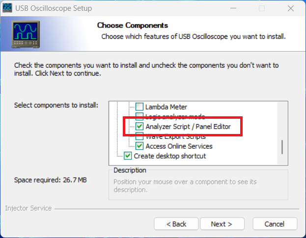
Step 1: Installing USB Oscilloscope
Download: Go to the download page and download the latest version of USB Oscilloscope. The program allows you to work not only with electrical waveforms you've recorded yourself, but also with those recorded by other USB Autoscope users and published publicly (for example, on the forum).
Installation Setup: To achieve our goal, it's essential to enable the "Analyzer script" option. This will ensure the installer installs all the necessary files and code samples, which will form the basis for the AI, into the "Documents" folder.
Step 2: Installing the Cursor AI Code Editor
Download: Visit cursor.com and install Cursor. This is a modern code editor with built-in AI support.
Authentication: After installation, the program requires authorization. The easiest way is to sign in with your Google account.
Trial Activation: To access the most powerful AI language models (such as Claude), which are best at creating scripts, you must activate the 14-day trial by providing your payment information. You can cancel your subscription at any time on cursor.com.
Creating a Script with AI
Once the tools are ready, you can move on to the most interesting part—directly interacting with the Artificial Intelligence.
Step 3: Setting up a Project in Cursor
Opening a Project: Launch Cursor and use the "Open Project" menu to specify the path to the "Documents/AutoscopeScripts" folder.
About Operating Modes: Cursor is actively developing. In particular, the update released immediately after the publication of this video brought changes to its interface. Therefore, it now has two main operating modes: "Agents" and "Editor." For beginners, we recommend switching the editor to "Editor" mode using the corresponding menu item located in the top left.
Loading Rules for the AI: In the left panel, open the "README_xx.md" file (selecting the desired language). This is key! While this file is open, the AI will constantly access it to adhere to the syntax and rules specific to USB Autoscope scripts.
Code generation settings: To begin creating a script, set the operating mode to "Agent" and select one of the latest Claude models (e.g., "Sonnet"). This configuration provides the best results when writing code.
Step 4: Formulating the Task (Prompt)
Communication with the AI happens naturally. We set a task (we write "prompt") in our native language:
"Hello, Artificial Intelligence. Write a script to display an engine RPM graph based on the crankshaft sensor signal. The script should request the channel number, the number of teeth per revolution, and the synchronization level."
After sending this task, the AI begins working: it analyzes the example files from the project, examines the rules in the "README.md" file, and generates a new script, creating a separate folder for it.
Step 5: Launching and testing the first version
Running the script: Launch the USB Oscilloscope program and open an oscilloscope file containing a signal suitable for analysis using the script you're creating. Load the newly created AI script from the "Analysis" menu.
Entering parameters: The program will run the script and display a dialog box where you enter the values for the corresponding parameters of the signal being analyzed (e.g., channel 1, 58 teeth for a 60-2 ring gear, synchronization level).
Result: The script processes the signal and plots a graph, in this case, of engine speed, and displays statistical information in the "Report" tab.
Gradually Improving the Script
The first version works, but we want to improve it. And AI will help us with this again.
Step 6: Making Edits via Dialog
Let's say we want to change the visual design.
Return to Cursor and write a new task:
"Change the graph color to blue and the grid color to gray."
The AI analyzes the request and makes changes to the existing code.
Step 7: Fixing Bugs
Sometimes, the AI can make mistakes. For example, after the first edit shown in this video, the graph turned red instead of blue. This happened due to a color format error (BGR instead of RGB).
- Wrong approach: If you give vague commands, like "The script isn't working correctly," the AI will only ask for more details.
- Right approach: Provide a detailed explanation: "Check the log file yourself." The graph color has changed from blue to red."
After receiving this command, the AI finds its error, corrects it, and updates the code.
Example - CAN Bus Analyzer protocol decoder
Using the new tools of USB Oscilloscope version 5, we have created a script for analyzing and decoding the CAN bus signal:
Key Features
Automatic detection of signal parameters:
- CAN_H and CAN_L signal levels
- Bitrate (support for standard and non-standard speeds)
- Start of activity
Full CAN decoding:
- Standard (11-bit ID) and extended (29-bit ID) frames
- RTR (Remote Transmission Request) messages
- Takes into account bit-stuffing
Noise immunity:
- Use of noise filtering due to adaptive averaging depending on the bitrate
Additional functionality:
- Automatic bookmarks on the waveform
- Detailed logging for diagnostics
- CRC-15 validation
- ACK detection
- Auto-calibration of bitTime
Requirements:
- USB Oscilloscope program
- 2-channel CAN bus recording (.mwf)
- Recommended sampling frequency: ≥1 MHz
Supported bitrates:
- Standard: 10k, 20k, 50k, 100k, 125k, 250k, 500k, 1M bps
- Plus: automatic detection of non-standard speeds
Usage:
- Open CAN bus waveform file
- Run script: Analysis → Execute Script
- The script will automatically detect all parameters
- Confirm or adjust settings
- Get decoded messages and bookmarks
Analyzer results:
=== CAN Bus Analyzer ===

Channels defined:
CAN_H: Channel 2 (Low=2.40V, High=3.39V)
CAN_L: Channel 1 (Low=1.62V, High=2.48V)

Bitrate defined: 500000 bps

=== Start CAN message analysis ===
Configuration:
- CAN_H: Channel 2
- CAN_L: Channel 1
- Bitrate [bps] 500000 bps
- Filter: All
=========================================

[0.002347s] ID: 0xC9, DLC: 7, Data: 04 10 41 04 50 41 82
[0.002549s] ID: 0xFFF1100 (EXT), DLC: 0
[0.002679s] ID: 0x41, DLC: 2, Data: 9A 08
[0.002813s] ID: 0x0, DLC: 0
[0.002903s] ID: 0x200, DLC: 1, Data: 00
[0.003009s] ID: 0x9FFE32 (EXT), DLC: 1, Data: 04
[0.003156s] ID: 0x1328208 (EXT), DLC: 0
[0.003296s] ID: 0x1A1, DLC: 7, Data: 04 14 10 50 41 04 10
[0.003500s] ID: 0xFFE50A0 (EXT, RTR), DLC: 0 (Remote Request)
[0.005124s] ID: 0x128, DLC: 2, Data: 08 41

=== Summary ===
Messages found: 10
Decoding errors: 0
=======================
Download the latest version CAN_Bus_Analyzer-v1.1.zip
Conclusions and Opportunities
This process clearly demonstrates that creating complex diagnostic tools is now accessible to everyone.
With the USB Autoscope + Cursor AI combination, you can:
Quickly implement ideas: Transform your ideas into working code without coding.
Gradually improve: Step-by-step add new functionality and fix errors through a simple dialogue with Artificial Intelligence.
Analyze data in a new way This approach allows you to look at data you previously examined manually from a completely new perspective, noticing patterns and nuances that were previously hidden from view.
We are confident that this technology will inspire many diagnosticians to create unique scripts that will make automotive diagnostics even more accurate and efficient.