Diagnosing motorcycles, buggies, ATVs, and snowmobiles
Most vehicle engines operate on similar principles and are designed in roughly the same way.
Mechanically, we have a crankshaft, connecting rods, pistons, valves, and so on.
Electrically, we have a roughly identical set of sensors and actuators, a fuel delivery system, and an ignition system.
Therefore, certain diagnostic principles and methods apply to virtually all engines, regardless of make and model. Fuel injection and ignition system is used in most cars, motorcycles, ATVs, buggies, snowmobiles, and scooters.

1. Engine Management System Sensors
Almost all modern engines are equipped with sensors. Based on these sensors, the control unit generates a command to start the engine and monitors all parameters while driving.
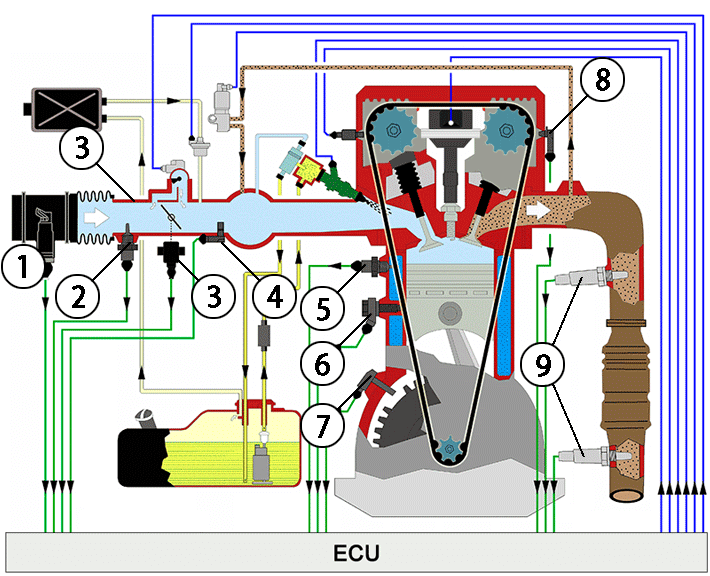
Figure 1. Engine Management System diagram
2. Fuel injection system
A motorcycle fuel injection (FI) system is an electronic system that precisely delivers fuel to the engine's combustion chamber, replacing a mechanical carburetor.
It uses sensors to monitor engine conditions such as throttle position, temperature, and RPM, and the engine control unit (ECU) to calculate the precise amount of fuel needed for optimal performance, fuel economy, and reduced emissions. The fuel is then sprayed by injectors as a fine mist, ensuring more efficient combustion than older carburetor systems.
3. Ignition System
The ignition timing system uses signals from the crankshaft position sensor and the RPM sensor (to determine engine speed). This control system sets the ignition timing to match engine operating conditions by adjusting a basic ignition timing map.
Most one-, two-, and four-cylinder engines use separate ignition coils.
Video of V-twin Ignition System operation on Yamaha TDM 900 motorcycle:

4. Diagnostics with USB Autoscope
Let's examine the engine operation of a 2004 Yamaha TDM 900 motorcycle. The USB Autoscope IV has 8 channels. We can simultaneously analyze the operation of the control system sensors and actuators in all engine operating modes.
Let's check the waveform:
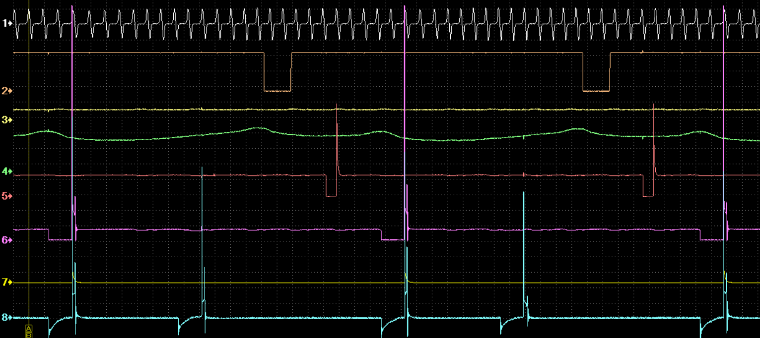
Figure 2. 8-channel recording on Yamaha motorcycle
- Crankshaft position sensor
- Cylinder identification sensor
- Throttle Valve Position Sensor
- Manifold Absolute Pressure Sensor
- Injector control pulse
- Ignition coil control signal
- First cylinder synchronization pulse
- High voltage pulses generated by an ignition coil
5. Adjusting the throttle valves
With the help of vacuum sensors Dx included to the USB Autoscope IV kit, it is possible to easily adjust the throttle valves of the intake manifold of the motorcycle at idle speed.
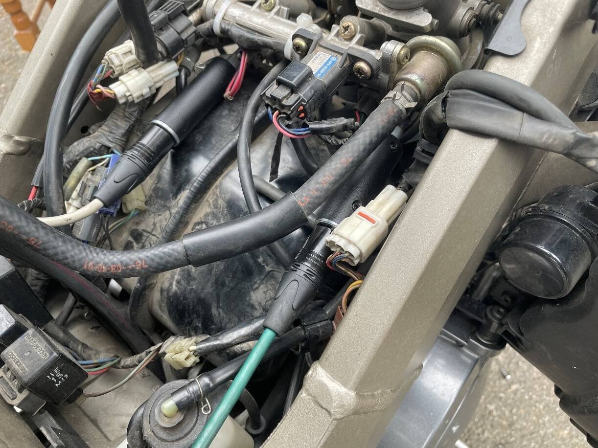
Figure 3. Use of 2 vacuum sensors Dx to adjust the throttle valves of the intake manifold
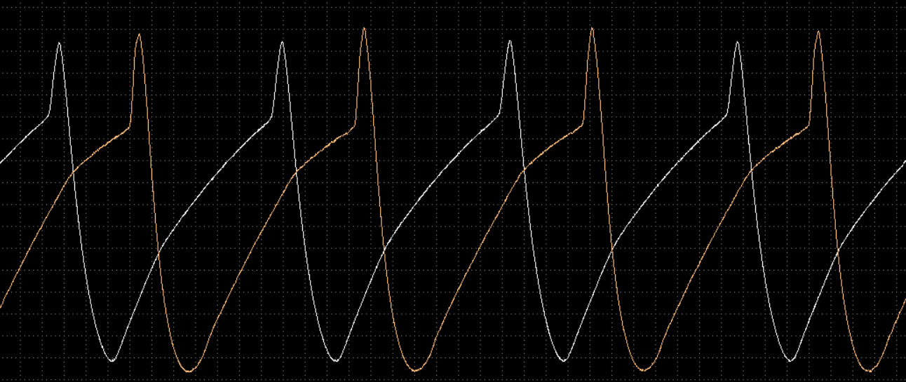
Figure 4. Graph of air pressure in the intake manifold after the throttle valves
Throttle Valves Synchronization video:
6. ElPower script
Designed to diagnose motorcycle starting and electrical systems, as well as measure relative compression in engine cylinders. Allows you to check the performance and condition of the following vehicle components and systems:
- Battery
- Starter
- Relative compression in engine cylinders
- Alternator
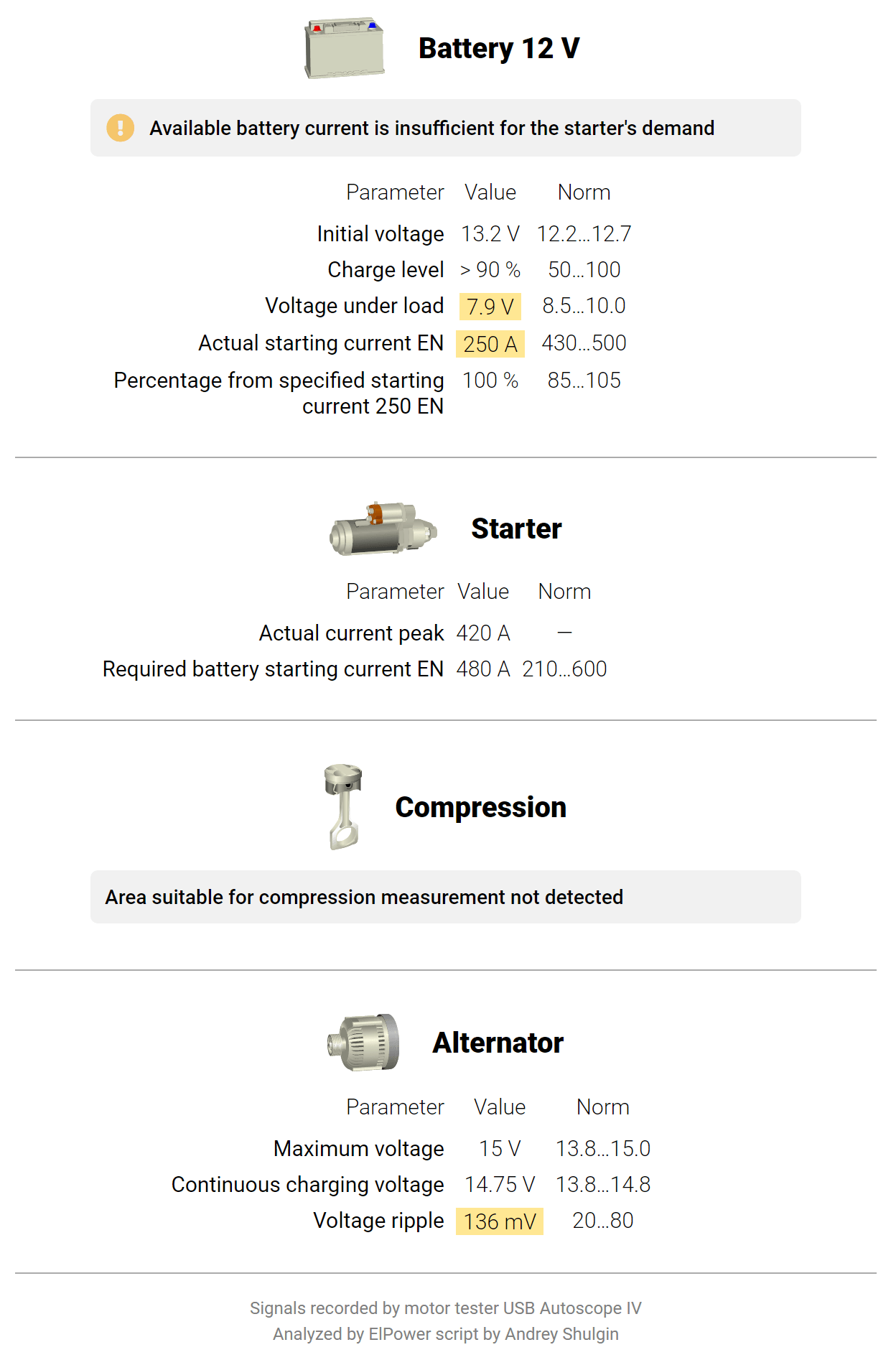
Figure 5. ElPower measurement results for a 2004 YAMAHA TDM900
7. Checking generator phases
Connect the device to the connector terminals. This is what the signal from three generator phases looks like
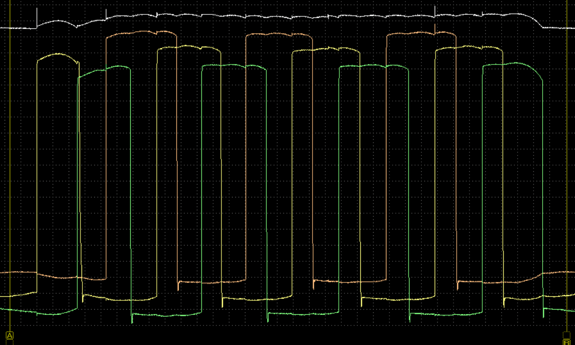
Figure 6. Signal from three generator phases
1 - Voltage 12V at the generator output
2, 3, 4 - Signals waveform from the three generator phases.