Crankshaft Position Sensor
The crankshaft position sensor is used to indicate the position and speed of the crankshaft. This information is used by the Power train Control Module (PCM) for ignition timing and fuel delivery.
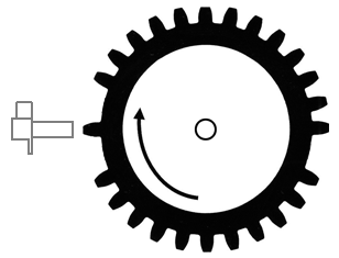
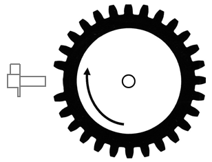
The sensor is located close to a disc or wheel containing a number of teeth or slots and affixed to, or cast as part of, the crankshaft. The distance between the sensor and the disc or wheel (often called a reluctor) is 0,8…1,0 mm, but verify specification with the manufacturer because this distance is critical to the proper operation of the sensor. The number of teeth can vary and depends on the number of cylinders and how accurate the system needs to be. One example uses 35 teeth for a 360 degree disc.

One tooth is often missing and is used to indicate piston position. The missing tooth often correlates to Top Dead Center (TDC) of cylinder number 1 (or the timing cylinder, if different).
The amplitude or voltage of the signal depends greatly on engine RPM and distance between the sensor and the reluctor. Specifications may vary, but the voltage should generally be more than plus or minus 6 V at idle and at least plus or minus 0,5 V while cranking the engine. The frequency of the signal will increase with engine RPM as well.


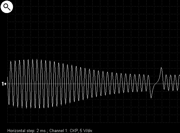
Signal from a Hall effect crankshaft position sensor on a VW Caddy 1.9SDI 2002

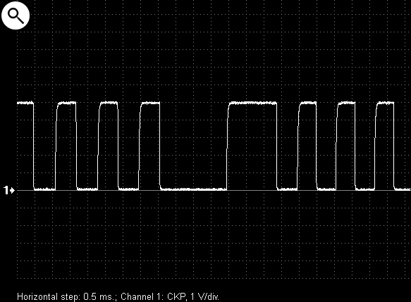
Zoomed signal from a Hall effect crankshaft position sensor

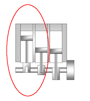
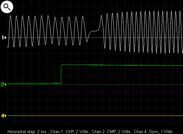
Output voltage waveforms from the crankshaft and camshaft position sensors on a Mitsubishi Pajero IV

Zoomed waveforms from the crankshaft and camshaft position sensors on a Mitsubishi Pajero IV
1 – signal from the camshaft sensor
2 – signal from the crankshaft sensor

Output voltage waveforms from a malfunctioning Hall effect crankshaft position sensor

Zoomed waveforms from a malfunctioning Hall effect crankshaft position sensor
1 – signal from the camshaft sensor
2 – signal from the crankshaft sensor

Signal from the crankshaft position sensor, the power supply circuit has an intermittent connection

Zoomed waveforms from the CKP sensor, the power supply circuit has an intermittent connection

Signal from a properly functioning crankshaft position sensor, but the reluctor or interrupter teeth are physically damaged


Zoomed signal

Output voltage waveform from a malfunctioning Hall effect crankshaft position sensor

Zoomed waveforms from malfunctioning CKP sensor

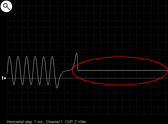
Output voltage waveform from a malfunctioning crankshaft position sensor

Zoomed waveforms from from a malfunctioning crankshaft position sensor

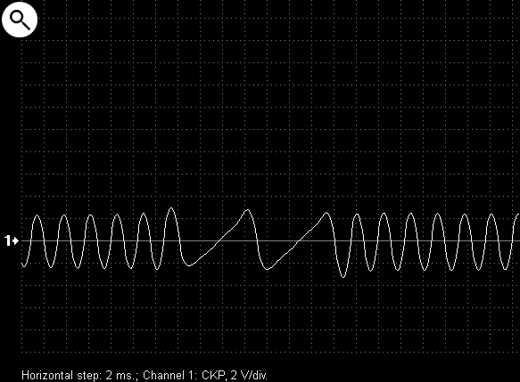
Typical waveform from an inductive crankshaft position sensor

1 – signal from the crankshaft sensor
2 – synchronization signal with the ignition spark in the cylinder #1

Zoomed waveform from an inductive crankshaft position sensor

Crankshaft position sensor signal, the reluctor wheel has 4 teeth without gaps


Zoomed waveform from crankshaft position sensor signal

Crankshaft position sensor signal from a Subaru engine
Zoomed waveform from crankshaft position sensor signal

Inductive sensor signal depends also on position and shape of the reluctor wheel teeth. For example, shown is a typical signal from the crankshaft position sensor on a Renault engine

1 – signal from inductive crankshaft sensor
3 – signal from a Hall effect camshaft sensor

Zoomed waveform from crankshaft position sensor signal
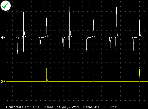
Additional pulse in signal of inductive crankshaft position sensor is generated by a permanent magnet installed at the end of one reluctor wheel tooth

4 – signal from the crankshaft position sensor
2 – synchronization signal with the ignition spark in the cylinder #1

Zoomed waveform from an inductive crankshaft position sensor signal

Shown is how the amplitude and frequency of pulses generated by an inductive sensor depends on engine rotational speed

Zoomed waveform

This is an example of how the amplitude from an inductive crankshaft position sensor is modulated or changes due to a change in distance between the reluctor wheel teeth and the sensor. In this case it is due to eccentricity or runout of the reluctor wheel relative to the crankshaft

Zoomed waveform

An example how rotational speed of the reluctor wheel influences amplitude and frequency of the inductive sensor signal. The crankshaft rotational speed is unstable due to low compression in two out of the three cylinders. (Chevrolet Spark 0.8i)
1 – signal from inductive crankshaft sensor
2 – signal from a Hall effect camshaft sensor
4 – synchronization signal with the ignition spark in the cylinder #1
Zoomed waveform

An example of an intermittent open circuit in the winding of an inductive crankshaft position sensor on Hyundai Elantra 1.6 2010

Zoomed waveform

Signal from an inductive sensor where the reluctor teeth are physically damaged

1 – signal from the crankshaft sensor
2 – synchronization signal with the ignition spark in the cylinder №1

Zoomed waveform

Signal from an inductive camshaft position sensor. The distance between the sensor and the reluctor teeth changes randomly due to camshaft bearing wear

1 – signal from the camshaft sensor
2 – signal from the crankshaft sensor


