Fuel injector
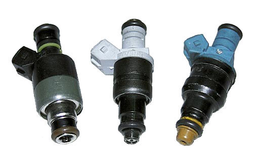
The fuel injector is a device with an electromagnetic valve, which, upon receiving an electrical impulse from the controller, injects fuel under pressure into the intake manifold. After the electrical impulse has expired, the injector shuts off the fuel supply.
The fuel injector is installed with one end in the fuel rail, the other in the opening of the intake manifold, the tightness of the connections is ensured by sealing rings.
The nominal resistance of the injector winding is from 11.0 to 13.4 Ω, at a temperature of 20 °C.
Application:
- Main fuel pump for fuel injected engines;
- Low pressure or lift pump for direct injection engines
- Lift pump for diesel engines


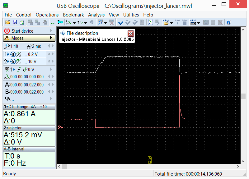


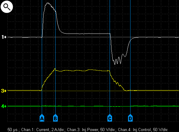
Typical voltage waveform on the control pin of a fuel injector. The current waveform in the circuit is also shown.
- 1 – voltage on the control pin
- 2 – current in the injector circuit
- A – start of the electrical injector pulse
- B – start of the actual fuel injection
- C – end of the electrical injector pulse
- D – end of the actual fuel injection
- A C – electrical injector pulse
- B D – actual fuel injection duration

Voltage and current waveforms in a properly functioning fuel injector circuit


Voltage and current waveforms of a malfunctioning injector. The injector pintle is sticking

- 1 – voltage on control pin
- 2 – current in the injector circuit


Voltage waveform on the control pin of a peak and hold injector circuit sometimes used on low resistance fuel injectors used in single point injection or Throttle Body Injection (Opel Vectra 1995 1.6).
- A B – Peak phase where the pintle is forced to move
- B C – Hold phase where the pintle is held open


Voltage waveform on the control pin of a peak and hold injector circuit sometimes used on low resistance fuel injectors used in single point injection or Throttle Body Injection (Ford Orion 1.4 1993).
- A B – Peak phase where the pintle is forced to move
- B C – Hold phase where the pintle is held open


Voltage waveform on the control pin of a peak and hold injector circuit sometimes used on low resistance fuel injectors used in single point injection or Throttle Body Injection. Magneti Marelli (Peugeot 405 1994 1.6).
- A B – Peak phase where the pintle is forced to move
- B C – Hold phase where the pintle is held open


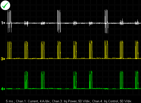
Voltage and current waveforms in injector circuit of a direct fuel injection system (VW Passat 1.8TSI 2008).
- 1 – current in the injector circuit
- 3 – voltage on supply pin
- 4 – voltage on control pin
- A B – peak phase when the pintle moves
- B C – hold phase where the pintle is held open


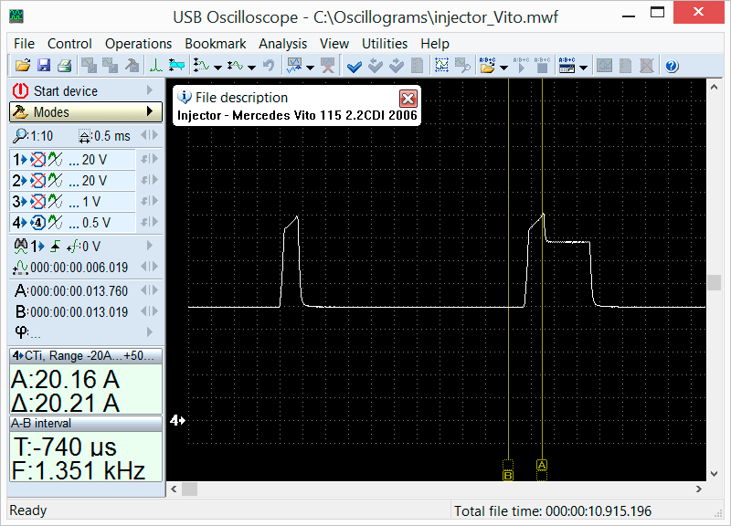
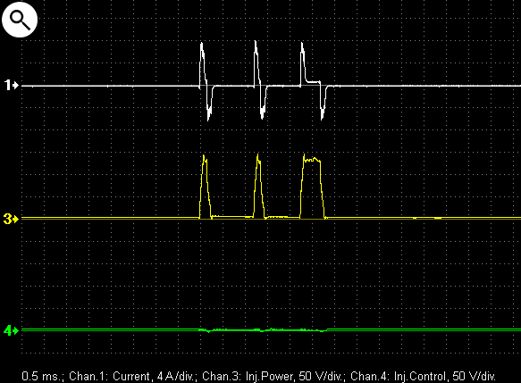
Voltage and current waveforms in a Common Rail electromagnetic diesel injector circuit.
- 1 – current in the injector circuit
- 3 – voltage on the supply pin
- 4 – voltage on the control pin
- A B – peak phase when the pintle is moving
- B C – hold phase where the pintle is held open
Voltage and current waveforms in a common rail piezoelectric diesel injector circuit (VW Touareg 3.0TDI 2005).
- 1 – current in the injector circuit
- 3 – voltage on supply pin
- 4 – voltage on control pin
- A B – injector opening
- C D – injector closing

