Classic cars diagnostics
Autoscope Technology makes it possible to test and diagnose faults in almost all vehicles produced in the 20th century.
These are vehicles that used a carburetor-based fuel delivery system.
The ignition system in such cars is a contact-type system with a mechanical distributor. Its main components include the ignition switch, battery, ignition coil, capacitor, contact breaker, distributor, and spark plugs.
Although this classic system is simple, it is less reliable than modern electronic systems due to rapid contact wear, which can cause starting issues, power loss, and increased fuel consumption.

1. Ignition system diagnostics
Several types of conventional ignition systems were installed on vehicles with gasoline internal combustion engines.

Figure 1. Conventional ignition system diagram with a mechanical contact breaker
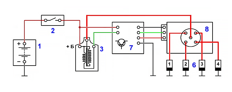
Figure 2. Contactless transistor ignition circuit diagram
- Battery
- Ignition switch
- Ignition coil
- Mechanical contact breaker
- Ignition distributor
- Spark plugs
- Transistor contactless breaker
- Ignition distributor with integrated Hall effect sensor / inductive sensor
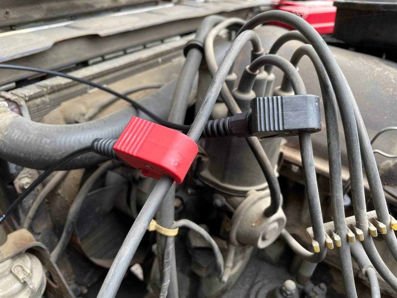
Figure 3. Connecting capacitive probes for ignition system diagnostics
The capacitive Red probe is connected to the high-voltage wire of the ignition coil
The capacitive Black synchronization probe is connected to the high-voltage wire of cylinder #1.
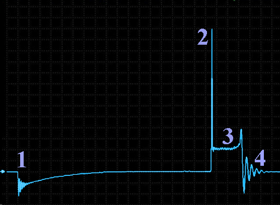
Figure 4. High voltage pulse waveform of a classic ignition system with a mechanical contact breaker
- Beginning of energy accumulation in the ignition coil's magnetic field (coincides with the moment the breaker contacts close)
- Breakdown of the spark gap between the spark plug electrodes and the beginning of the spark (coincides with the moment the breaker contacts open)
- Spark combustion section.
- End of spark combustion and the beginning of damped oscillations
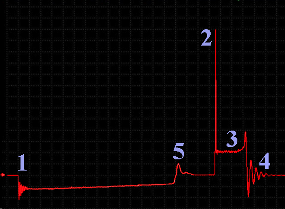
Figure 5. High-voltage pulse waveform from a contactless transistor ignition system
- The start of energy accumulation in the ignition coil's magnetic field, coinciding with the opening of the commutator's power transistor
- The breakdown of the spark gap between the spark plug electrodes and the start of spark combustion, coinciding with the closing of the commutator's power transistor
- Spark ignition section
- End of spark ignition and the beginning of damped oscillations
- The commutator's transition to current limiting mode in the ignition coil's primary winding at 6...8 A.
The USB Autoscope software allows you to simultaneously monitor all ignition pulses. PlugIn Ignition diagnostics:
The ignition system's operation is described here
2. Typical ignition system faults
This document describes in detail cases of ignition system malfunction.
Let's look at several practical examples of malfunctions provided by owners of the USB Autoscope motortester.
Waveform library from the forum with detailed descriptions of malfunctions
Malfunction examples from the forum:
Spark plug insulator breakdown fault
Malfunction: Burning time before and after replacing the coil
Malfunction of the ignition system distributor
Malfunction breakdown outside the combustion chamber of cylinder №3
3. Adjusting the ignition timing
The main faults in the ignition system are incorrect ignition timing.
Ignition timing correction under heavy engine loads is mechanically controlled by a centrifugal regulator, which adjusts the ignition advance angle based on the stiffness of the springs and the mass of the flyweights, depending on the engine crankshaft speed.
When the engine load changes while its speed remains constant, the centrifugal regulator does not alter the ignition advance, even though under these conditions (constant speed and variable load) the ignition timing should change. To compensate for this, the centrifugal regulator is supplemented with a vacuum regulator.
In the past, ignition timing adjustment was checked using a stroboscope.
Autoscope technology allows this measurement process to be fully automated.
Proper ignition timing adjustment contributes to:
- Increased power: Improved acceleration dynamics and higher top speed
- Increased torque: Facilitates acceleration and overtaking
- Reduced fuel consumption: With optimal components, it can provide fuel savings
- Correction of factory errors: Correction of manufacturer-inherent faults
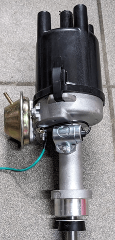
Figure 6. Distributor
Ignition timing testing using USB Autoscope IV and Px script
4. Engine diagnostics using a cylinder pressure sensor. Script Px
Until recently, checking the mechanical condition of an engine required a lot of time and attention.
Here’s an incomplete list of what had to be inspected:
- Valve timing phases
- Alignment marks of the crankshaft and camshaft
- Intake and exhaust valve clearances
- Camshaft lobe wear
- Shaft runout in support bearings
- Cylinder compression
- Condition of intake and exhaust valves
Now, Autoscope technology has made this entire process completely automated.
Px v3.24 Script — analyzes key parameters of the cylinder, intake and exhaust systems, valve timing mechanism, and ignition timing control system.
The primary purpose of the Px script is to test the engine's mechanical components and verify the proper operation of its subsystems. The script operates by automatically analyzing the cylinder pressure graph obtained using a sensor installed in place of the spark plug.
5. Reference Px Graphs – Cylinder Pressure Waveform Catalog
This forum thread about Cylinder Pressure Graphs on InjectorService.com.ua is dedicated to creating a structured catalog of reference cylinder pressure waveforms (Px).
The thread includes good reference waveforms, forum users contribute by uploading .mwf files of pressure waveforms and discussing results for engines from various car brands and models, forming a collaborative technical database for automotive diagnostics.