Express Diagnosis by Exhaust Pulsations
1. Introduction
This method is based on the analysis of exhaust pulsation failures. It has been known for a long time and many have already used it by putting their hand to the exhaust pipe to determine whether there are misfires in the engine cylinders. SenX Technology was the first to identify problematic cylinders by exhaust using their FirstLook sensor and oscilloscope.

Figure 1. FirstLook engine diagnostic sensor
To analyze the exhaust gas flow pulsations, the FirstLook sensor pipe had to be inserted into the exhaust pipe and its output signal recorded together with the spark signal of the cylinder #1.

Figure 2. FirstLook sensor connection

Figure 3. FirstLook sensor signal
But this technique has not received wide distribution due to the complexity of the resulting signal form. After all, against the background of additional pulsations of different sizes, it is not so easy to determine in which cylinder there is a misfire and in which there is not.
2. Connection procedure
This technology was improved by Yuri Ignatenko (nickname Gnat), who proposed to connect a "funnel" to the piezoelectric sensor instead of a pipe, originally intended for pouring liquids into bottles. It was recommended to place such a funnel with a sensor opposite the exhaust pipe at a short distance, placing, for example, a box of the required height under the sensor.
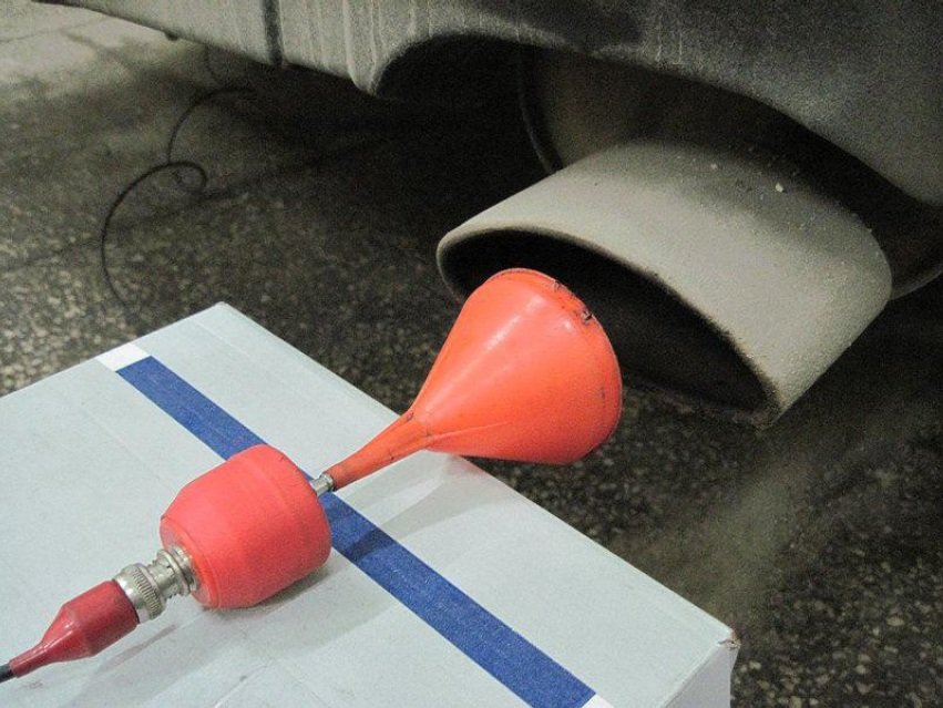
Figure 4. Use of a funnel with a sensor opposite the exhaust pipe at a short distance
The differences in the signals have now become clearly noticeable: against the backdrop of an almost flat line reflecting the normal operation of the cylinders, the misfire appears as a clearly visible spike. But the polarity of the pulse reflecting the misfire turned out to be unusual.
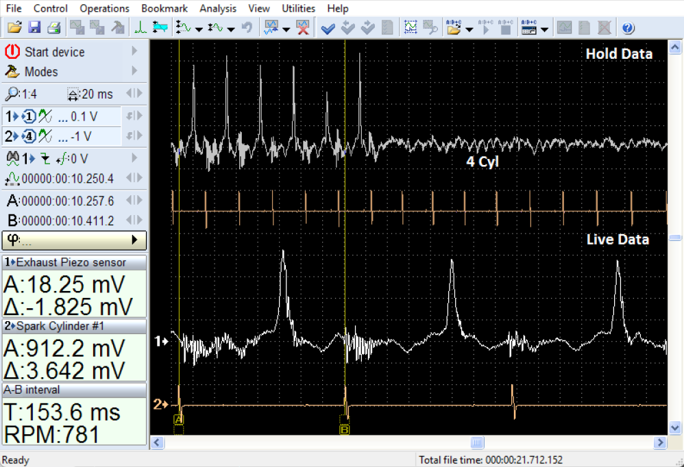
Figure 5. Exhaust piezo sensor waveform
It was natural to want to improve this technology to make it more convenient to use. During the testing of various options, a design emerged from a plastic hose rolled into a ring, designed for laying electrical cables.
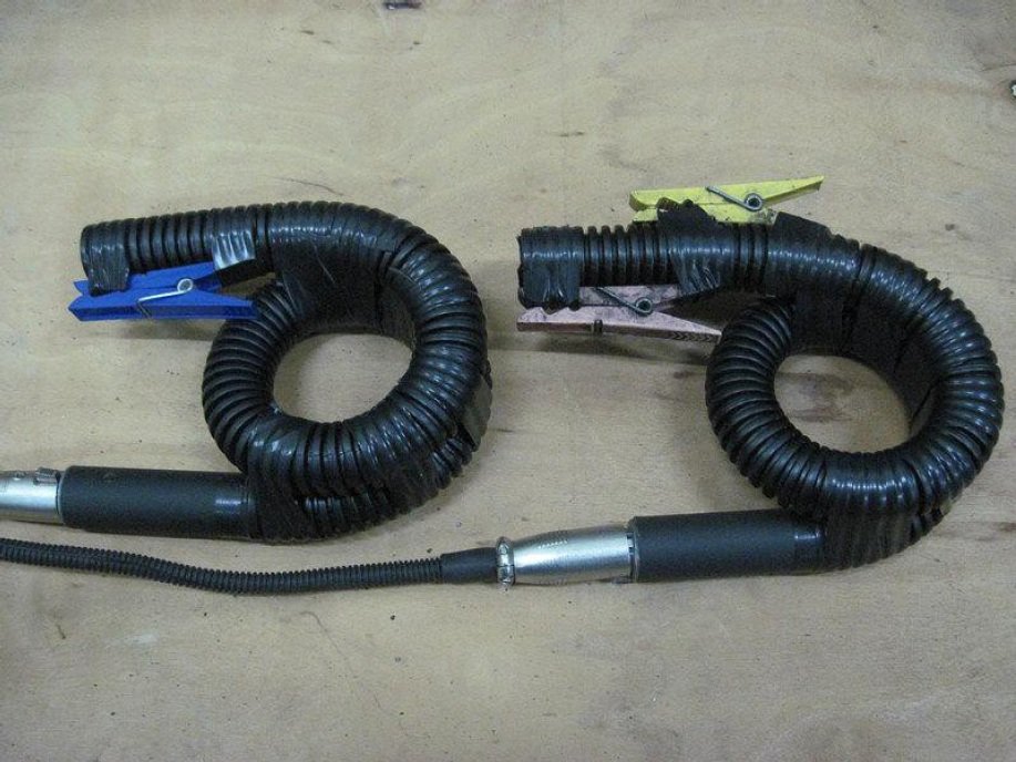
Figure 6. Two Dx sensors in corrugated hoses
Anyone can make such a device on their own: from one meter of corrugated hose you can make two devices for the Dx vacuum sensor included in the USB Autoscope kit. Everything depends on the rigidity of the plastic from which the hose is made and on the ability to roll it into a ring of the desired size. One and a half turns are convenient because such a design allows you to securely fix the sensor on the exhaust pipe; at the same time, the sensor does not touch the floor, and its electrical connector is directed towards the engine, which reduces the required cable length for connecting to the oscilloscope. In addition, such a design prevents moisture from water vapor present in the exhaust from getting into the sensor. The diameter of the corrugated hose is selected approximately equal to the diameter of the Dx sensor. Two clamps allow you to choose the depth of installation of the hose in the exhaust pipe, since the exhaust pipes on different cars vary in diameter and have different decorative tips.

Figure 7. Two Dx sensors inserted to the exhaust pipes
The depth of the hose installation in the exhaust pipe affects the amplitude and, partially, the shape of the received signal. With the correct depth, small pulsations will be visible on the horizontal signal line, and the misfire will look like a significant dip in the signal, which is well consistent with the logical perception of misfire.
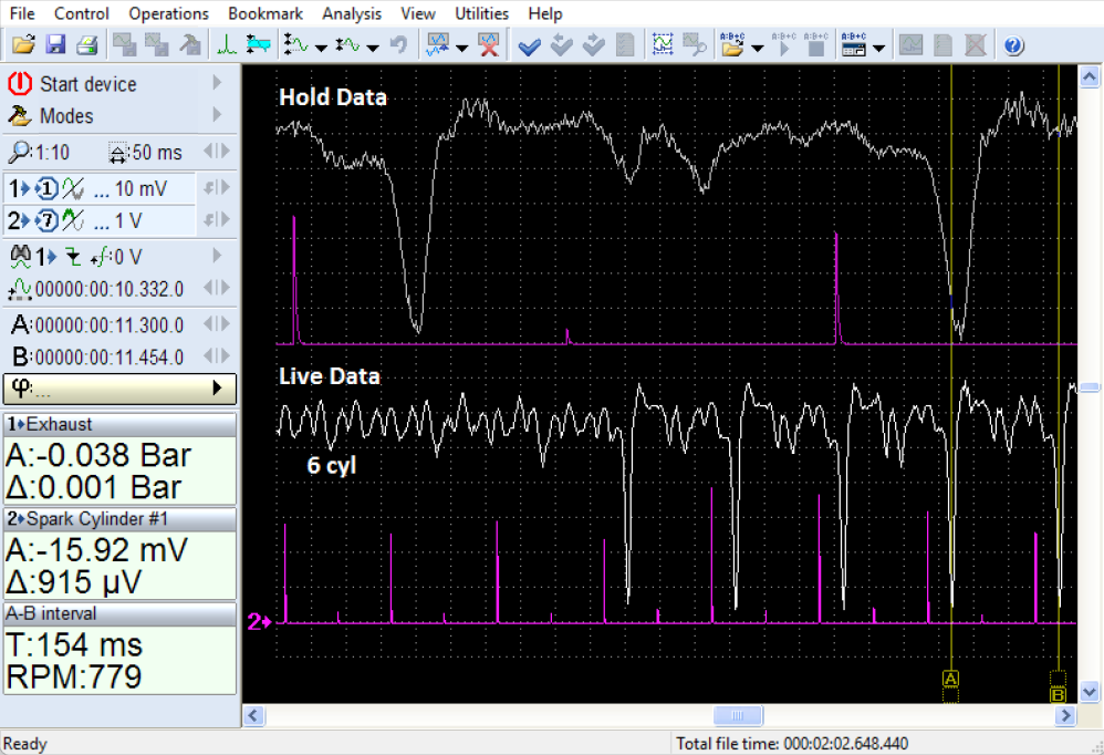
Figure 8. The depth of the hose installation in the exhaust pipe affects the amplitude
If the hose is installed deeper in the exhaust pipe, the amplitude of the pulsations from the working cylinders increases, while the amplitude of the pulsations arising from misfires increases slightly. As a result, the difference between the pulsations from the working and non-working cylinders becomes less noticeable.
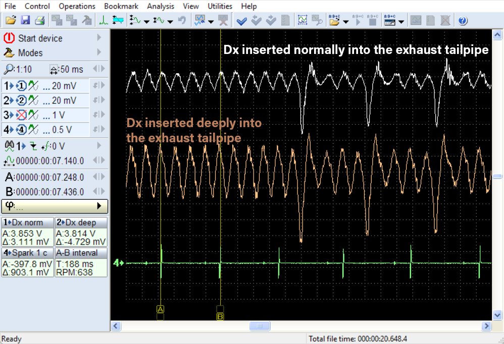
Figure 9. Dx sensor normally vs deeply inserted to the exhaust pipe
But small pulsations from the working cylinders are useful for visually counting the cylinder numbers relative to the spark of the cylinder #1.
The signal from the piezo sensor can display similar processes in a slightly different way - with a positive and negative pulse of almost the same amplitude.
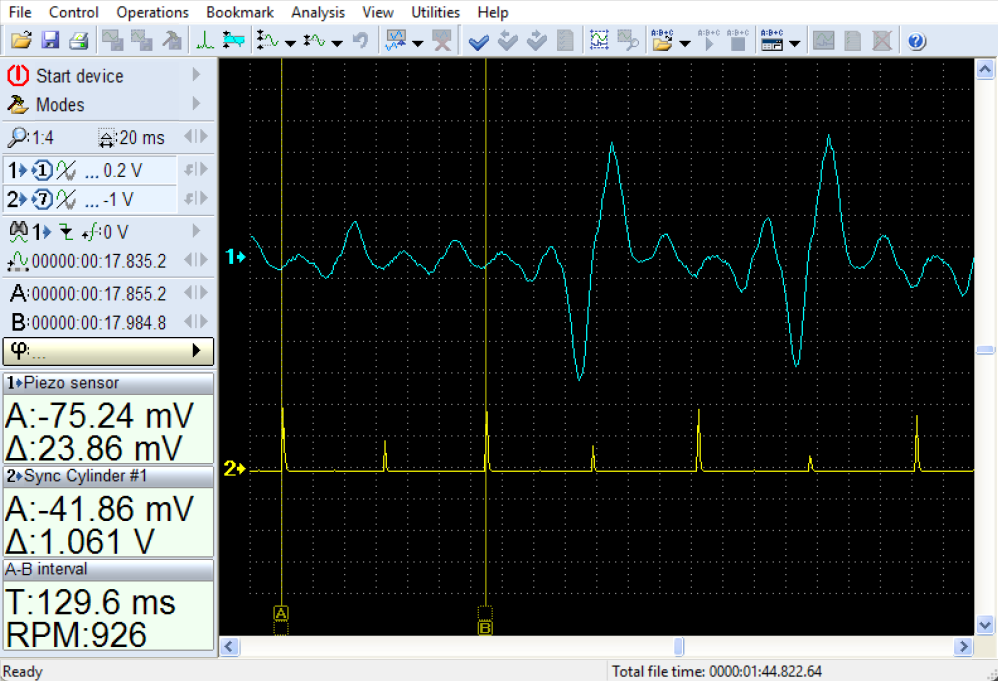
Figure 10. The signal from the piezo sensor
This may be inconvenient when analyzing some faults, for example, related to the operation of the valve mechanism. If the sensor shows double pulses, but in reality there are only single ones, then it will be difficult to determine the differences in some faults.

Figure 11. The signal from the Dx sensor
Sensors that display actual pressure, such as the Dx sensor, are capable of showing the correct signal shape. In contrast, sensors based on the piezoelectric effect, which only show pressure changes, introduce some distortion to the true signal shape. Depending on how they are connected to the exhaust pipe, Dx and piezoelectric sensors may display the exhaust pulsation signal differently.

Figure 12. Differences between Dx and piezoelectric sensor exhaust pulsation signals
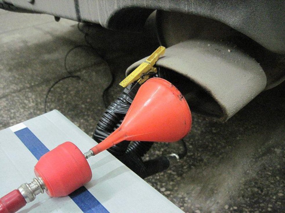
Figure 13. Connection of piezo sensor
3. Dx amplifier
The main advantage of piezo sensors is their high sensitivity, but the sensitivity range of the USB Autoscope channels is quite sufficient to display signals from any of the listed sensor types. Therefore, an amplifier for the Dx sensor is only needed when working with the old version of the USB Oscilloscope v.3 program, which few people use now.

Figure 14. Dx sensor vs Dx + Amplifier signal
The measurement procedure is as follows. To set up the oscilloscope to view the exhaust pulsation signal or record the signal for later viewing, you can select the two-channel mode. Set horizontal zoom to 5…10 ms per division, depending on the engine idle speed and the width of the monitor screen, so that the screen fits two spark marks for the cylinder #1. For USB Autoscope IV, it is better to select the maximum voltage limit of ±6 V in the channel #1 setup panel.
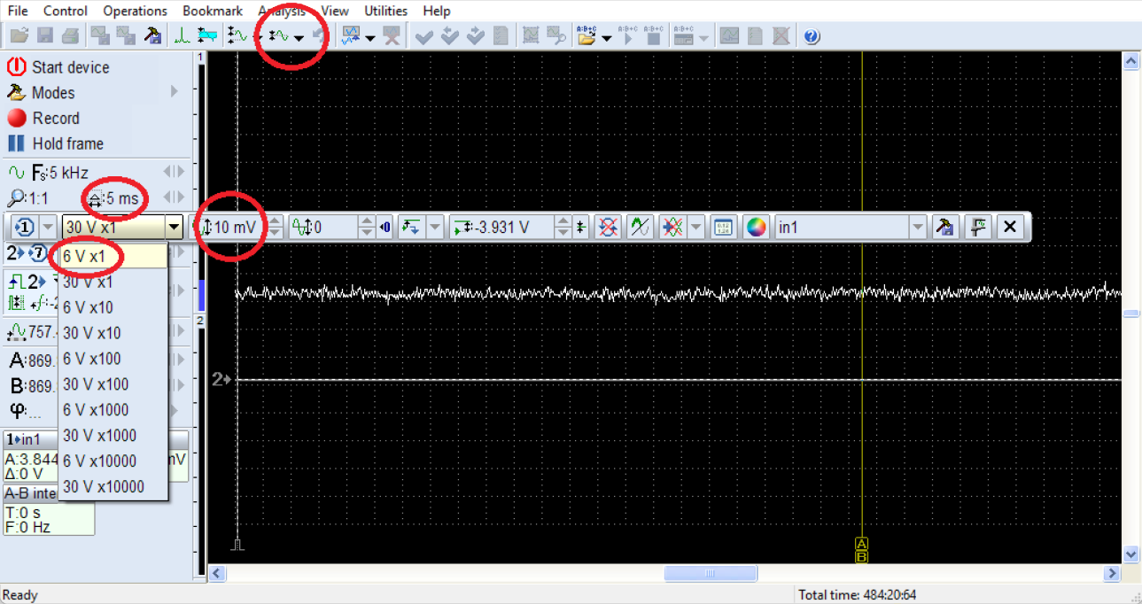
Figure 15. Set up the oscilloscope
Then you need to connect the Dx sensor to the input #1 of USB Autoscope IV using an extension cable, through which power will be supplied from the oscilloscope to the sensor, and a signal from the sensor to the oscilloscope. Such an extension cable is easy to make yourself, or you can buy it from the oscilloscope manufacturer. If you have a regular BNC extension cable, you can connect it to the signal cable of the Dx sensor, and supply power from 9 V battery.
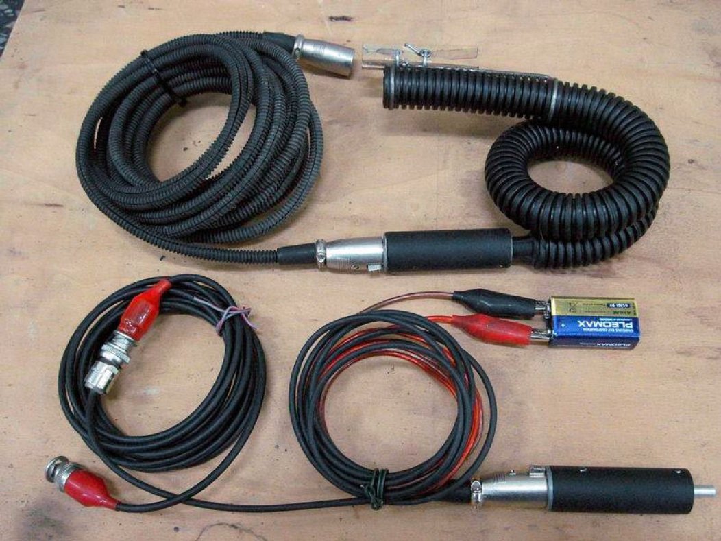
Figure 16. Use of an extension cable for Dx sensor
If after power is supplied to the sensor, the horizontal line of channel #1 goes beyond the screen, then it will be most convenient to return it to the display area using the menu "Operations => Arrange waves".
The second channel is needed for visually linking misfires to the spark of cylinder #1. To do this, in the channel #2 panel, select analog input #7, and connect the synchronization probe to the high-voltage wire of cylinder #1. If the engine is equipped with Coil-on-plug ignition, then you can use the inductive probe Lx-M from the USB Autoscope IV kit.
Next, you need to attach the Dx sensor to the exhaust pipe and start the car engine. There should be small pulsations on the horizontal line of channel #1. Their number between the spark marks of cylinder #1 should be equal to the number of engine cylinders. If these pulsations do not look clear enough, then you can insert the sensor a little deeper into the exhaust pipe.
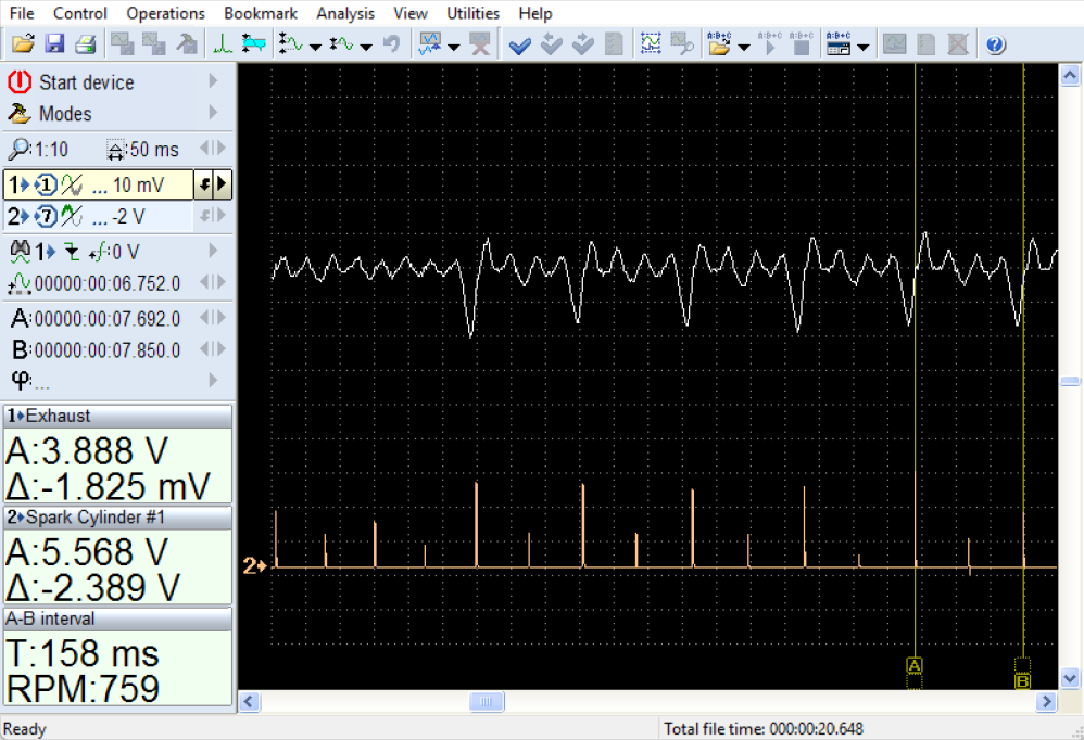
Figure 17. Dx sensor inserted to the exhaust pipe during idle
At first, it may be difficult to determine the number of the cylinder in which misfires occur. Then you can disconnect any of the cylinders to show another misfire on the waveform from the now known cylinder. This will help to easily determine the number of the cylinder with misfires if the order of operation of the cylinders and the number of the artificially disconnected cylinder are known. With experience, additional disconnection of cylinders may be necessary only when analyzing pulsations in multi-cylinder engines.
4. Dx panel
In order for the oscilloscope to display cylinder numbers on the screen, you can use the Dx_Panel analyzer panel.
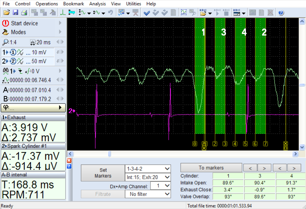
Figure 18. Vacuum pulsation graph, analyzed using the analyzer panel “Dx_Panel”
Although this panel is intended for analyzing intake manifold vacuum pulsations, it can also be used to analyze uneven exhaust pulsations. To ensure that the firing order of the cylinders matches the pulsations displayed on the graph, the markers should be set not at the ignition marks of cylinder #1, but in the middle between those marks.
For clarity, and to better understand the moment when a misfire occurs at the exhaust pipe, a recording is provided with an additional signal from the in-cylinder pressure sensor Px installed in the spark plug hole of cylinder #4. The engine was running at idle.
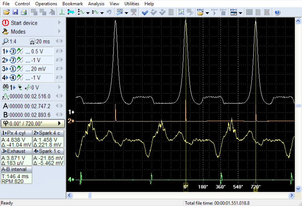
Figure 19. Recording with an additional signal from the in-cylinder pressure sensor Px installed in the spark plug hole of cylinder #4
It is clearly visible here that the appearance of the misfire signal at the exhaust pipe lags behind the start of the exhaust stroke by approximately 180° of crankshaft rotation. Additionally, the delay for the pulse to travel through the exhaust pipe is about 30 ms. Therefore, this method is more suitable for detecting misfires at engine idle.
Despite some limitations, this method does not require complex vehicle connections and is well-suited for rapid diagnostics. It allows the detection of cylinders with even isolated misfires. It can easily determine whether the misfires are linked to specific cylinders or occur randomly—for example, when caused by an incorrect air-fuel mixture. When troubleshooting by swapping individual ignition coils or spark plugs, it helps to determine whether the fault moves to other cylinders. It is also useful for identifying misfires that occur briefly, such as those appearing a few seconds after a cold engine start.
5. Daewoo Matiz diagnostics
When using a 4-channel recording with additional signals from the intake manifold vacuum and injector control, even more diagnostic information can be obtained. For example, consider a 2-second recording during the startup of a 3-cylinder Daewoo Matiz engine. This data made it possible to detect misfires (indicated by negative pulses appearing synchronously with two cylinders, and later with only one cylinder) as well as valve operation deviations in one of the cylinders (indicated by positive spikes in the exhaust signal from that specific cylinder).
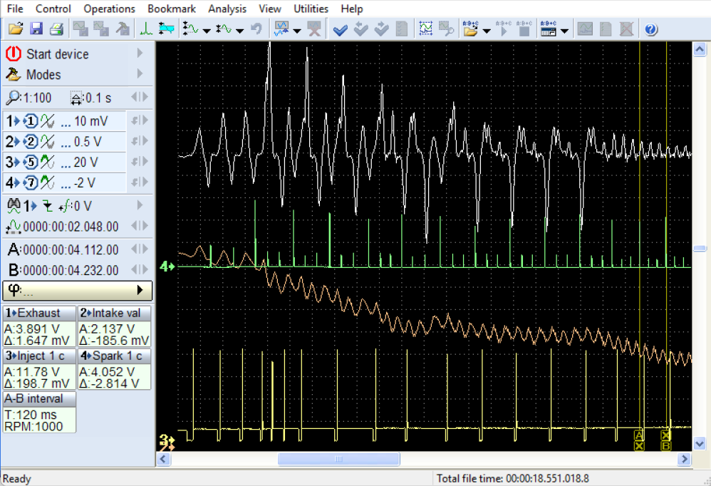
Figure 20. Misfires in cylinders #2 and #3
The main issue here is misfires in cylinders #2 and #3 caused by worn spark plugs. Although there were brief valve operation deviations during engine startup, they did not affect engine performance under normal operating conditions.
6. Chevrolet Cruze diagnostics
The exhaust pulsation recording on a Chevrolet Cruze helped identify the cause of rough operation in its 4-cylinder engine. The engine would start cold without any issues, but after 40 to 60 seconds of running, it would begin to misfire. Following a brief warm-up, it would return to normal operation until the next cold start. The engine control unit only registered error code P0300—indicating random or multiple cylinder misfires.
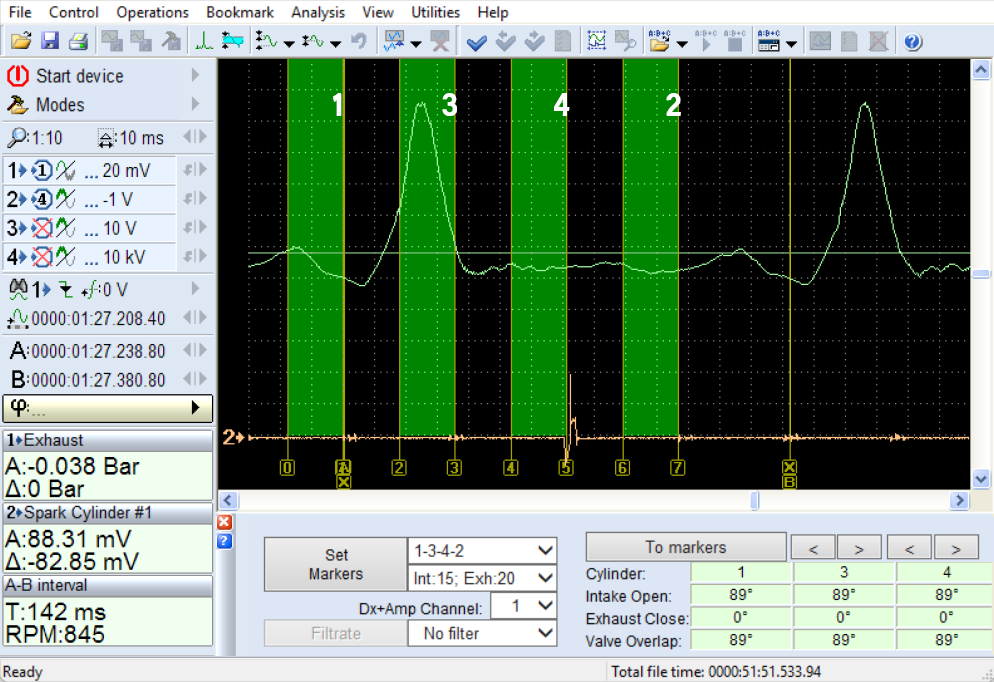
Figure 21. Improperly sealed exhaust valves
It should be noted that the cylinder numbers shown on the pulsation graph above do not directly indicate the problematic cylinder, as the positive polarity of the exhaust pulsations does not signify a misfire, but rather a gas breakthrough through the exhaust valves. According to the engine’s firing order, when cylinder 3 is in the exhaust stroke, cylinder 4 is undergoing the power stroke—at which point gases can escape into the exhaust system through improperly sealed exhaust valves.
7. Conclusion
Exhaust pulsation analysis offers a fast and non-invasive method for evaluating engine performance and identifying misfires. By using appropriate sensors and diagnostic tools, such as the Dx pressure sensor, technicians can accurately interpret exhaust signals to distinguish between functioning and malfunctioning cylinders. This method enhances diagnostic efficiency and reduces the need for complex engine disassembly, making it a valuable technique in modern automotive diagnostics.
Authors:
Andrew Bezhanov