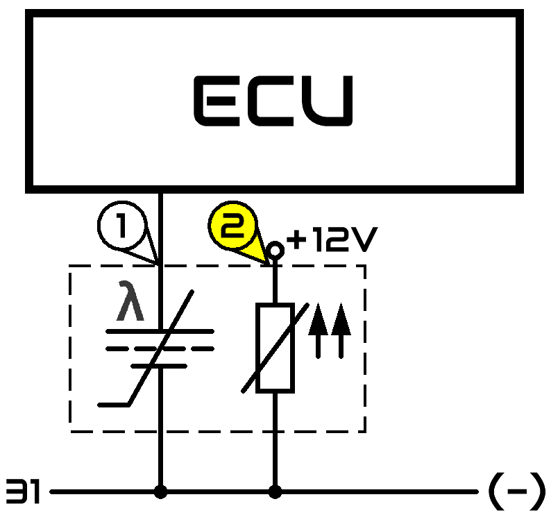
O2 Sensor
The Zirconia Lambda sensor which is by far the most common narrow band sensor is used to determine the air/fuel ratio in the combustion chamber by reading the oxygen demand of the residual exhaust gas. The sensor tip is made of catalytic material, is hot, and is subject to hot exhaust gas. This exhaust gas may contain some unburned or partially burned fuel if the air/fuel ratio in the combustion chamber is “rich”. To complete the combustion of the unburned or partially burned fuel in/at the catalytic material at the hot sensor tip, additional oxygen is needed. This additional oxygen travels through the membrane at the sensor tip and causes a potential (voltage) difference to develop. This voltage potential is then read by the computer and interpreted as a rich condition. If the air/fuel ratio in the combustion chamber is “lean”, no additional oxygen is needed and a voltage potential does not develop. This low voltage condition is interpreted by the computer as a lean condition.

A very rare sensor is the Titania sensor. This sensor is a true oxygen sensor and it varies it’s resistance according to the oxygen content in the exhaust stream.
The sensors can be mounted before as well as after the catalytic converter.
Application:
- narrow band lambda sensor
- wide band lambda or air/fuel ratio sensor


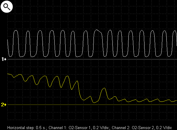
The distortions of the output signal of the O2-sensor from the bank 2 cylinders are caused by uneven air/fuel ratios in the various cylinders in this group
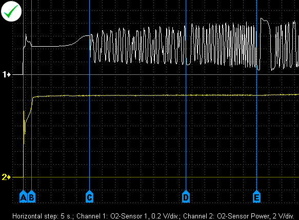
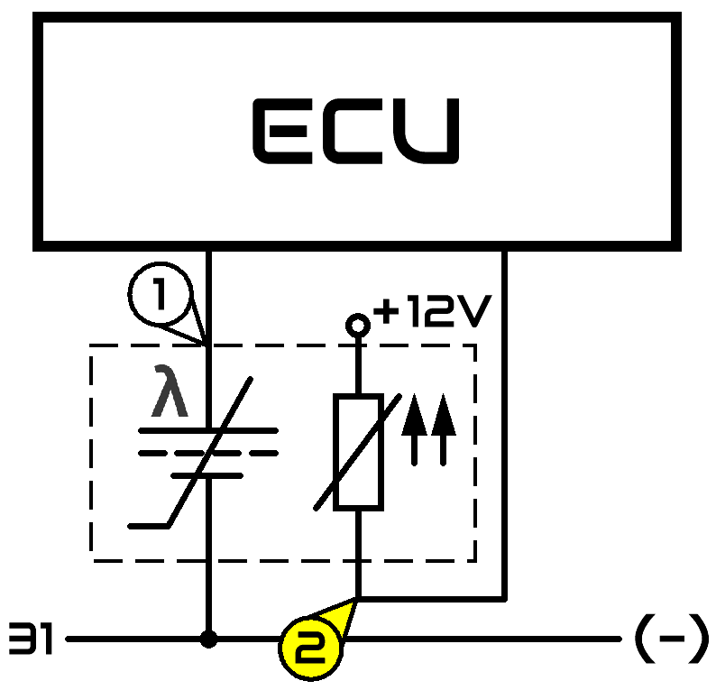
Output voltage waveforms from a properly functioning zirconia narrow band lambda-sensor and power supply sensor heater
1 – signal from a lambda sensor mounted before the catalytic converter
2 – the power supply for the sensor heater
A – engine start
B – running at idle; the sensor is not hot enough to function properly
C – the sensor is hot enough to start working
D – start of smooth throttle valve opening
E – closing of throttle valve

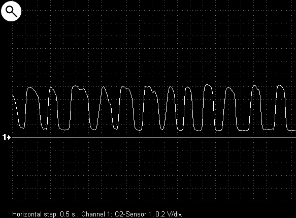
Engine running at idle
Engine running at high RPMs
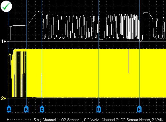
Output voltage waveforms from a properly functioning zirconia narrow band lambda-sensor and power supply sensor heater
1 – signal from lambda-sensor mounted before the catalytic converter
2 – PWM control signal for the the sensor heater
A – engine start and running at idle
B – the engine control unit increased the duty cycle of the sensor heater
C – the sensor is heated sufficiently to work properly
D – start of smooth throttle valve opening
E – closing of throttle valve


Output voltage waveforms from a properly functioning zirconia narrow band lambda sensors

Engine running at idle
1 – signal from lambda-sensor mounted before the catalytic converter
2 – signal from lambda-sensor mounted after the catalytic converter
A – engine start and running at idle
B – start of smooth throttle valve opening
C – closing of throttle valve
Engine running at high RPMs
Sharp throttle closing at 3000 RPM


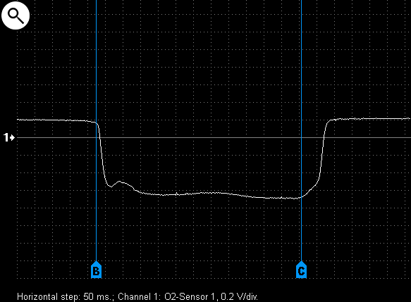
Output voltage waveform from a malfunctioning zirconia narrow band lambda-sensor. The sensor is not working
A – engine start and running at idle
B – start of smooth throttle valve opening
C – deceleration and running at idle
D – snap throttle
Output voltage waveform from a malfunctioning lambda-sensor. The malfunction causes the sensor to output a negative voltage
A – engine running at idle
B – turning off the fuel injectors during deceleration after snap throttle
C – turning on the injectors at the end of deceleration


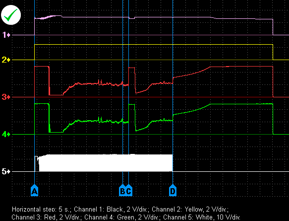
Voltage waveforms from wires of wide band lambda sensor BOSCH LSU (VW Golf 1.6 2003)

1 – black wire
2 – yellow wire
3 – red wire
4 – calibration resistor
5 – white wire
A – engine start and running at idle
B – snap throttle
C – deceleration
D – engine shut off

Voltage waveform of the measurement cell and current of the pump cell of wide band lambda sensor BOSCH LSU, received in differential measuring mode
1 2 – output voltage of the measurement cell
3 4 – voltage drop on calibration resistor of the sensor
Video
Waveform examples
 USB Oscilloscope program is required for waveform playback
- O2-Sensor - Mitsubishi Lancer 1.6 2005
- O2-Sensors bank1 - Toyota Avensis 1.8i 2007
- O2-Sensors bank1 - Opel Vectra C 2.2 2006
- O2-Sensor + Heater Current - Mitsubishi Lancer IX
- O2-Sensor - Siemens resistive type
- Faulty O2-Sensor - generates negative voltage
- Faulty O2-Sensor - slow response
- O2-Sensors bank1 and bank2 - dirty fuel injectors


