Conventional Ignition System
In this Article:
- Introduction
- Primary ignition diagnosis
- Secondary ignition diagnosis
- Typical waveforms from conventional ignition systems
- Distributor type electronic ignition
- Typical waveforms from electronic ignition systems
- Distributor ignition with the ignition coil built in to the distributor
- Two-distributor ignition
- Double plug distributor ignition
- Video
- Waveform examples
Introduction
Distributor ignition systems have been with us for approximately 90 years. The DI-type ignition system consists of the following components: ignition coil, distributor, spark plugs, high voltage wires and some means of controlling the primary ignition circuit. The primary circuit of the ignition coil can contain: points, points controlling a transistor, the transistor being controlled by some other means (breaker less) or electronic ignition. In point type ignition systems the current in the primary circuit is controlled by a mechanical switch (or breaker). The mechanical points may control a switching transistor which opens and closes the primary circuit of the ignition coil. In breaker less transistor and electronic ignition a Hall effect, VRS (Variable Reluctance Sensor) or an optical sensor may be used to control the switching transistor.
Current flows from the positive terminal of the battery, through the ignition switch and / or relay, through a fuse and on to the positive terminal of the ignition coil. The current returns to the battery through the negative terminal of the ignition coil, on through the switching device (points or a transistor) through the vehicle chassis, and to the negative terminal of the battery. While current is flowing in the primary circuit a magnetic field builds up in the ignition coil. Due to the inductance of the ignition coil it takes some time (1…6 ms, depending on design) for the primary current to reach its nominal value. When the primary current flow is interrupted, the magnetic field collapses rapidly (in about 20 µs) and a high voltage is induced in the primary winding (CEMF Counter electro motive Force). This voltage is transformed in to a very high voltage in the secondary winding. The amplitude of this voltage depends on the turns ratio (commonly 100:1). A 300 V primary voltage, therefore, will be 30’000 V in the secondary winding. The voltage will only build until the break down voltage of the spark gap is reached – the firing voltage of the spark plug.
Primary ignition diagnosis
In order to diagnose the primary ignition the measuring adapter must be connected to the control pin of the primary circuit of the ignition coil and connected to input #5 of USB Autoscope IV. To display the current waveform from the primary circuit, current transducer CTi-50 must be connected to input #4 of USB Autoscope IV and attached to the supply or control wire of the ignition coil. Select “Modes => Ignition => Ignition_Primary” in the USB Oscilloscope program. Start the engine. A primary ignition system waveform will be displayed.
Secondary ignition diagnosis
Connections for secondary waveform diagnosis:
- One of the red probes from the DIS Cx 6 set connects to the input "In+", located on USB Autoscope IV front panel, and is attached to the ignition coil high voltage wire, as close as possible to the ignition coil
- Black synchronization probe connects to the input "In Synchro", and is attached to the high voltage wire going to cylinder #1. Attach the probe as close as possible to the spark plug

Figure 1. Connection of high-voltage probes
- In the USB Oscilloscope program, select “Modes => Ignition => Ignition_Classic” or “Modes => Ignition => Ignition_Parade”;
- Start the engine
Once the engine is started, the red LED on the front panel should be lit. If the green LED is lit, the connections are backwards.
If all connections are correct, the USB Oscilloscope program will display a parade waveform, showing firing voltage, spark voltage and burn time for each cylinder.
Normal operating parameters for an ignition system are as follows:
- Firing voltage (also known as break down voltage) – on the average 4…18 kV
- Spark voltage (also known as burn voltage) – 1…4 kV
- Spark duration (also known as burn time) – 1…2 ms
The above values will change according to the air / fuel ratio and cylinder pressure.
Typical waveforms from conventional ignition systems
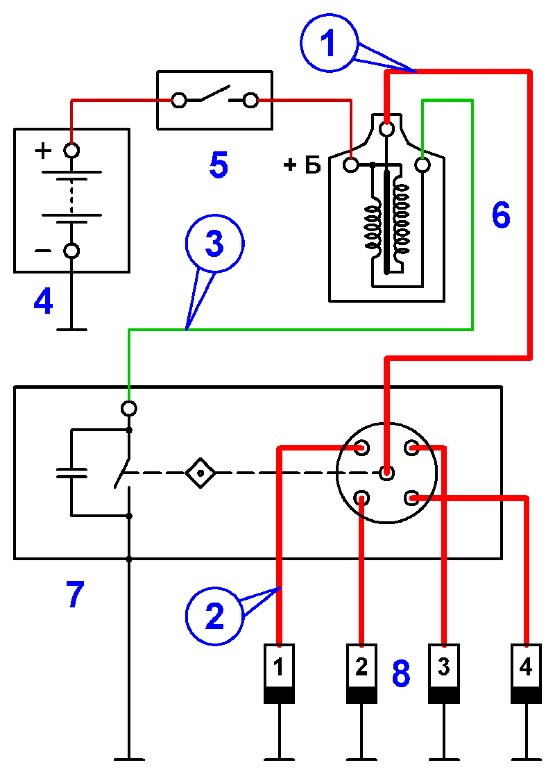
Figure 2. Wiring diagram for a conventional ignition system
This system uses points to control the primary current.
- Attachment point for the capacitive probe Cx
- Attachment point for the sync probe Sync
- Connection point for obtaining a primary waveform
- Battery
- Ignition switch
- Ignition coil
- Distributor equipped with points
- Spark plugs
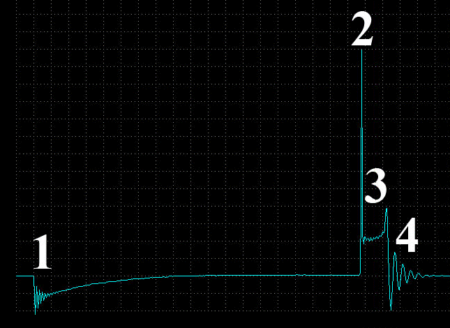
Figure 3. Typical secondary waveform from a conventional ignition system, equipped with points
- The points close, primary current starts to flow and a magnetic field is being built up in the ignition coil
- The points open and a high voltage is induced. The height of the firing line represents the voltage needed to initiate a spark. (Cause ionization or break down of the spark gap)
- The spark line. The height represents the voltage needed to sustain the spark and the length of the line the duration
- The spark is extinguished. The beginning of the intermediate section with some dampened oscillations
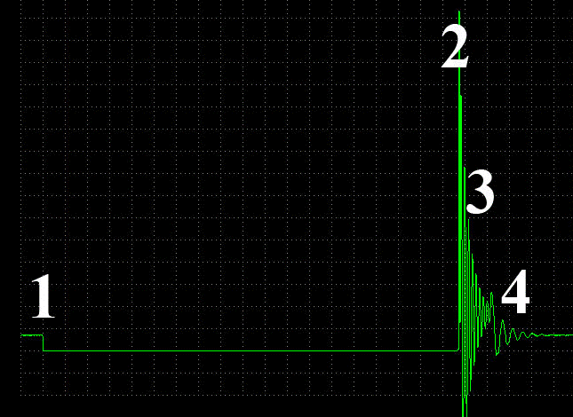
Figure 4. Typical primary waveform from a conventional ignition system, equipped with points
1. The points close, primary current starts to flow and a magnetic field is being built up in the ignition coil.
2. The points open and a high voltage is induced. The height of the firing line represents the voltage needed to initiate a spark. (Cause ionization or break down of the spark gap)
3. The spark line. The length of the line represents the spark duration
4. The spark is extinguished. The beginning of the intermediate section with some dampened oscillations
3-4. The oscillations seen are the result of current flow between he capacitor in parallel with the points and the primary windings. These oscillations actually strengthens the spark and may be absent if the coil is connected backwards
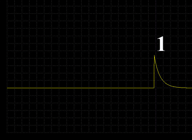
Figure 5. Typical waveform from the sync probe attached to the timing cylinder
1. This probe is a synchronization probe and will, therefore, show the strobe waveform
Distributor type electronic ignition
The connections are the same as for conventional ignition.
Typical waveforms from electronic ignition systems
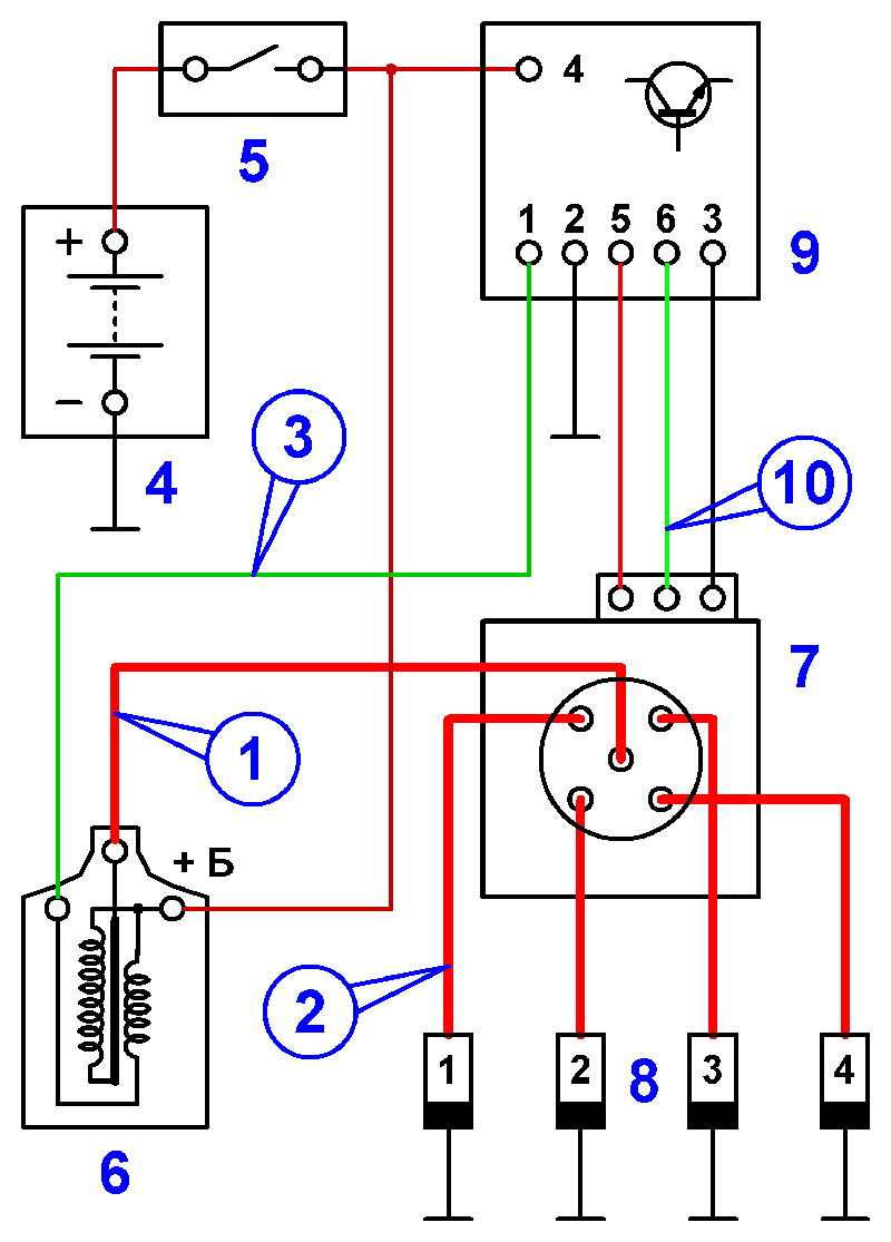
Figure 6. Wiring diagram for distributor ignition. This system switches the primary circuit using a transistor
- Attachment point for the capacitive probe Cx
- Attachment point for the sync probe Sync
- Connection point for obtaining a primary waveform
- Battery
- Ignition switch
- Ignition coil
- Distributor containing a Hall sensor
- Spark plugs
- Ignition control module, also known as the ICM
- Connection point for observing the signal from the Hall sensor in the distributor

Figure 7. Distributor ignition secondary waveform
- The transistor in the ICM turns on, primary current starts to flow and a magnetic field is being built up in the ignition coil
- The ICM limits the primary current once a predetermined value is reached. Commonly 6…8 A. 2 is often called the "current limiter hump"
- The transistor turns off and a high voltage is induced. The height of the firing line represents the voltage needed to initiate a spark (cause ionization or break down of the spark gap)
- The spark line. The height represents the voltage needed to sustain the spark and the length of the line the duration
- The spark is extinguished. The beginning of the intermediate section with some dampened oscillations

Figure 8. Distributor ignition primary waveform
- The transistor in the ICM turns on, primary current starts to flow and a magnetic field is being built up in the ignition coil
- The ICM limits the primary current once a predetermined value is reached. Commonly 6…8 A. 2 is often called the "current limiter hump"
- The transistor turns off and a high voltage is induced. The height of the firing line represents the voltage needed to initiate a spark (cause ionization or break down of the spark gap)
- The spark line. The height represents the voltage needed to sustain the spark and the length of the line the duration. Notice that there are very few oscillations in this part of the waveform, compared to point-type ignition. This is because there is very little capacitance across the switching device
- The spark is extinguished. The beginning of the intermediate section with some dampened oscillations
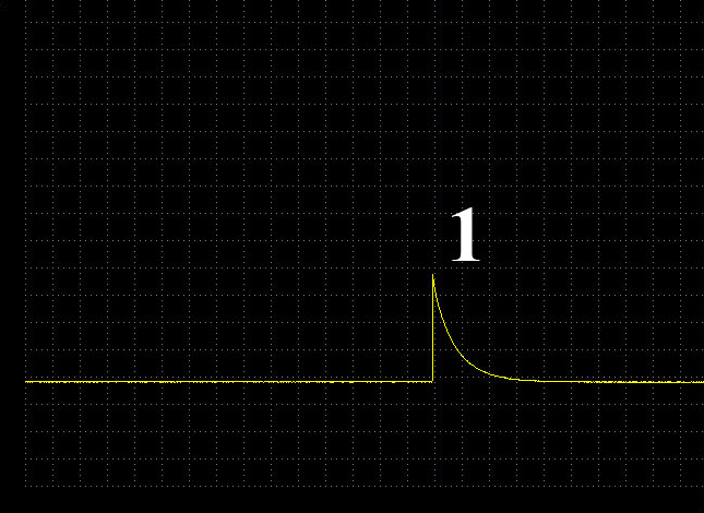
Figure 9. Typical waveform from the sync probe attached to the timing cylinder
1. This probe is a synchronization probe and will, therefore, show the strobe waveform

Figure 10. Hall sensor waveform
Make sure the Hall switch will pull the waveform all the way to ground. Intermittent problems can be traced to failures to completely pull the signal to ground.
Distributor ignition with the ignition coil built in to the distributor
Other than the built in ignition coil, this system is similar to normal distributor ignition. Some Asian built cars used this arrangement.
Connections for secondary waveform diagnosis:
- connect Cx-M capacitive probe to the input "In+", located on USB Autoscope IV front panel, and attach it as close to the ignition coil as possible
- the black synchronization probe connects to the input "In Synchro", and attach to the high voltage wire going to cylinder #1. Attach the probe as close as possible to the spark plug
- Start the engine. If all connections are correct, the oscilloscope will display a parade waveform, showing firing voltage, spark voltage and burn time for each cylinder
Two-distributor ignition
Some V8 and V12 engines manufactured in the 90’s by Audi and BMW were equipped with two distributors, one for each cylinder bank. These two systems operated independently of each other.
Diagnosis is the same as for a normal distributor ignition, except one, then the other ignition system must be examined.
Double plug distributor ignition
Some engines were equipped with double plug distributor ignition (some Nissan’s equipped with the "Z" engines). The double plug distributor ignition uses two ignition coils, but one distributor equipped with a special cap and rotor.
These engine were so equipped to improve combustion and lower emissions, especially at idle. The engines were equipped with one “intake” and one “exhaust” spark plug. The two spark plugs does not fire simultaneously, the exhaust plug fires a few milliseconds later. The exhaust spark plugs does not fire once a higher RPM is reached, to minimize noise.
Except for the points made above, diagnosis is the same as for normal distributor ignition. Do remember that the exhaust side does not fire at higher RPM.


