Coil-on-Plug Ignition System
In this Article:
- Introduction
- Principle of operation
- Typical malfunctions
- The order of diagnostics of individual ignition
- Circuit of individual ignition and points of connection for diagnostics of the system
- Diagnostics by the primary voltage waveform
- Diagnostics by the secondary voltage waveform
- Diagnostics by the secondary voltage waveform with help of the capacitive probe
- Diagnostics by the secondary voltage waveform with help of the inductive probe
- Video
- Waveform examples
Introduction
The majority of modern petrol engines are equipped by Coil on Plug (COP) individual ignition systems. This ignition system differs from classical and DIS ignition system by that each spark plug in such system is served by individual ignition coil. Depending on the device of the core, individual ignition coils share on two types – compact, and rod.

Figure 1. Compact (left) and rod (right) individual ignition coils installed directly above spark plugs
Structurally, individual ignition coils can be make as separate elements, or incorporated in modules by two, three or four ignition coils in one module.

Figure 2. The ignition module consisting of four compact individual ignition coils. The module is installed directly above spark plugs
In most cases, individual ignition coils are installed directly above spark plugs. But exist engines where ignition coils are connected to spark plugs by means of high-voltage wires.
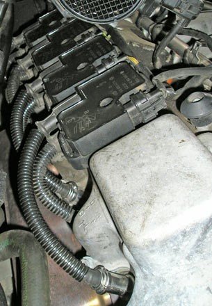
Figure 3. The ignition modules consisting of two individual ignition coils, connected to spark plugs by means of high-voltage wires
On the shown example, each cylinder of the engine is equipped by two spark plugs served by own module
Principle of operation
The individual ignition coil by one running cycle of the engine generates one ignition spark. Therefore, in individual ignition systems is required synchronization of coils work with position of a camshaft.
At submission of the voltage to the primary coil, the current starts to flow by a primary coil and because of that in the core of the coil changes the value of the magnetic flux. Change of the magnetic flux value in the core of the coil leads to occurrence of the voltage of positive polarity on a secondary coil. Because the speed of increasing of the current in the primary coil is slow, the voltage arising on a secondary coil is small – according 1…2 kV. But in the certain conditions the voltage value can be sufficient for untimely occurrence of the spark between electrodes of a spark plug and as consequence, too early ignition of the air/fuel mixture. In order to prevent possible damages of the engine due to untimely occurrence of the spark, formation of the spark between electrodes of a spark plug at submission of a voltage to a primary coil should be excluded. In the individual ignition systems, occurrence of this spark is prevented by means of built-in diode EFU to the ignition coil switched consistently in a circuit of a secondary coil.
At the moment of closing of the output ignition cascade, current in the primary circuit sharply interrupts, and the magnetic flux promptly decreases. This fast change of the magnetic flux value is causes to occurrence of the high voltage on a secondary coil of the ignition coil (under certain conditions, the voltage on a secondary coil of the ignition coil can achieve 40…50 kV). When this voltage achieves the value providing formation of the spark between electrodes of a spark plug, the compressed in the cylinder air/fuel mixture is ignited from the spark between electrodes of a spark plug.
Typical malfunctions
Overall dimensions of individual ignition coils are small, so that manufacturers of engines can to place them directly above spark plugs. But because of the small sizes reliability of coils decreases. As consequence, individual ignition coils often fail, and first of all – isolation of a secondary coil. Damage of a coil isolation is causes to breakdown spark between coils inside of the ignition coil. The ignition coil with such malfunction is usually capable to provide burning of the air/fuel mixture in the cylinder when the engine works at small loadings or at idle. But at greater loadings to the engine a spark formation stops, and the cylinder served by such coil, stops to work. It is possible to find this malfunction by the the primary or the secondary waveform. Attribute of the breakdown between a coil isolation of the ignition coil is absence of damped oscillations in the finish of burning of the primary or the secondary waveform.
The order of diagnostics of individual ignition
Each spark plug of the engine equipped by individual ignition system, is served by own ignition coil and own ignition control module. For this reason, diagnostics of individual ignition system goes consistently – ignition systems of each cylinder is diagnosed serially, one by one, as separate ignition systems (after the ending of diagnostics of one ignition coil the diagnostician starts to diagnostics of the following ignition coil, etc.).
The basic tested parameters at diagnostics of individual ignition are:
- presence of damped oscillations in the end of a site of burning of a spark between electrodes of a spark plug
- duration of the period of accumulation of energy in a magnetic field of the individual ignition coil (usually 1.5…5.0 ms depending on the design of the coil)
- duration of burning of a spark between electrodes of a spark plug (usually 1.5…2.5 ms depending on the design of the coil). It is necessary to consider, that if the duration of spark burning between electrodes of a spark plug on any mode of engine work will be less than 0.5 ms because of the fail ignition coil, than the spark between electrodes of a spark plug will arise, but air / fuel mixture from such spark possibly will not be ignited
Circuit of individual ignition and points of connection for diagnostics of the system
The circuits of individual ignition are shown below. There are shown points of connection oscilloscope probe and high-voltage transducers to the diagnosed coil, for diagnostics of system by the primary and secondary waveforms.

Figure 4. The circuit of the individual ignition system with the external ignition control module (circuit is shown for one cylinder)
- Point of connection of a black "crocodile" clip of the oscilloscope probe
- Point of connection of the lead of oscilloscope probe
- Point of connection to a signal in a secondary circuit with help of the universal capacitive probe "Cx-M"
- Installation site of the universal inductive probe "Lx-M" for connection to the signal in the secondary circuit
- Vehicle battery
- Ignition switch
- The compact individual ignition coil without the built-in ignition control module
- Spark plug
- The engine control module (or the ignition control module)
Inside of the individual ignition coil can be built-in ignition control module.
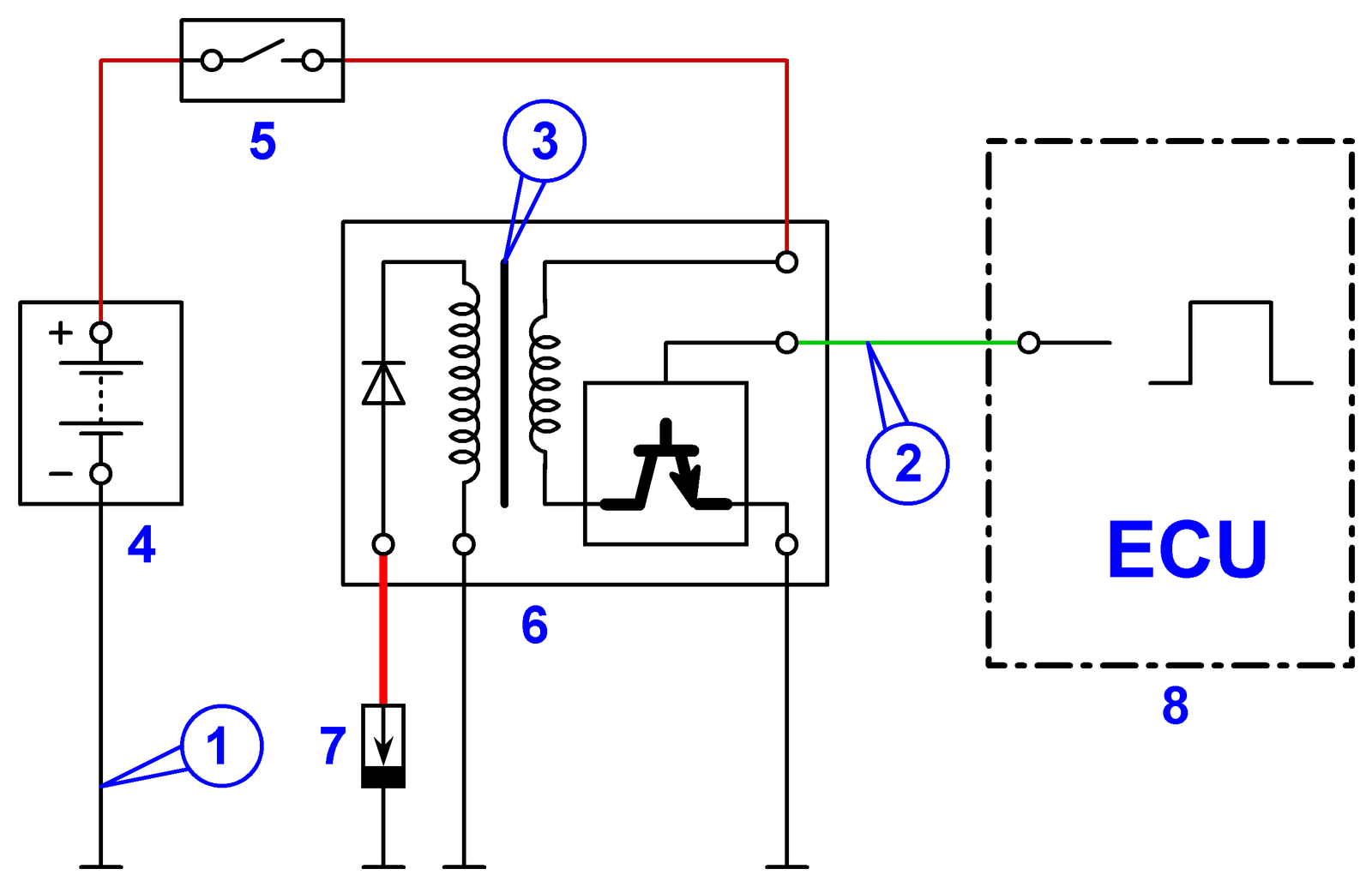
Figure 5. The circuit of individual ignition system with the built-in ignition control module (the circuit is shown for one cylinder)
- Point of connection of a black "crocodile" clip of the oscilloscope probe.
- Point of connection of the lead of oscilloscope probe
- Point of connection to a signal in a secondary circuit with help of the universal inductive probe "Lx-M"
- Vehicle battery
- Ignition switch
- The compact individual ignition coil or rod individual ignition coil with the built-in ignition control module
- Spark plug
- The engine control module
Diagnostics by the primary voltage waveform
For diagnostics of the individual ignition coil by the primary voltage, it is necessary to see the waveform of the voltage on the operating lead of the primary coil of the ignition coil with the help of oscilloscope probe.
To get the primary voltage waveform on the operating lead of the ignition coil, the measuring adapter must be connected to the control pin of the primary circuit of the ignition coil and connected to input #5 of USB Autoscope IV. To display the current waveform from the primary circuit, current transducer CTi-50 must be connected to input #4 of USB Autoscope IV and attached to the supply or control wire of the ignition coil.
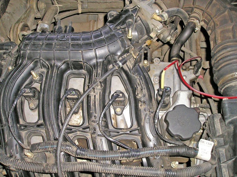
Figure 6. Connection of oscilloscope probe to the operating lead of the primary coil of the individual ignition coil
Start the diagnosed engine. In the window of the program "USB Oscilloscope" necessary to choose "Modes => Ignition => Ignition_Primary". Now, in the window of the program the primary voltage waveform of the diagnosed ignition coil will be displayed.

Figure 7. The voltage waveform on the operating lead of the primary coil of the serviceable individual ignition coil
- The moment of opening of the power transistor of the ignition control module (the beginning of accumulation of the energy in a magnetic field of the ignition coil)
- The moment of closing of the power transistor of the ignition control module (the current in the primary circuit sharply interrupts and arising of the breakdown of a spark interval between electrodes of a spark plug)
- A site of burning of a spark between electrodes of the spark plug
- The damped oscillation arising after of the ending of burning of a spark between electrodes of the spark plug
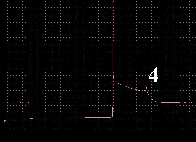
Figure 8. The voltage waveform on the operating lead of the primary coil of the faulty individual ignition coil
An attribute of malfunction is absence of damped oscillations after the ending of burning of the spark between electrodes of the spark plug (the site is noted by a symbol "4")
Inside of some types of individual ignition coils is built-in ignition control module. The operating lead of a primary coil of such ignition coils is situated inside of the ignition coil and because of that inaccessible to connect the lead of oscilloscope probe to the operation lead of the ignition coil. It makes impossible diagnostics of such individual ignition coil by the primary voltage waveform. In this case, diagnostics of the ignition coil makes with help of the universal capacitive probe "Cx-M" or universal inductive probe "Lx-M" by the secondary voltage waveform.
Diagnostics by the secondary voltage waveform
At diagnostics of ignition systems by the secondary voltage waveform applying capacitive probe. In case when application of the capacitive probe is impossible, applying the inductive probe. Application of the capacitive probe more preferably as the signal received with its help more precisely repeats the voltage waveform in a secondary circuit of diagnosed ignition system.
Diagnostics by the secondary voltage waveform with help of the capacitive probe
The capacitive probe for diagnostics of the individual ignition coil by the secondary voltage waveform is the universal capacitive probe "Cx-M". To get the signal with help of the capacitive probe is possible only in the event that created by a secondary coil of the ignition coil the electric field is not in the metal screen. Such ignition coils are some compact individual ignition coils without the built-in ignition control module.

Figure 9. Compact individual ignition coils
For diagnostics of the individual ignition coil by the secondary voltage waveform with help of the universal capacitive probe "Cx-M":
- the connector of the probe must be connected to the input In+, located on the front side of the USB Autoscope IV
- install universal capacitive probe "Cx-M" to the case of the diagnosed ignition coil so that the sensitive side of the plate (black color) was as closer as it possible to a secondary winding of the coil
- start the engine
- in the program “USB Oscilloscope”, select “Modes => Ignition => COP”

Figure 10. Diagnostics of the compact individual ignition coil by the secondary voltage waveform with help of universal capacitive probe "Cx-M"
Now, in a window of the program will be displayed the secondary voltage waveform of the diagnosed ignition coil.

Figure 11. Diagnostics of the compact individual ignition coil by the secondary voltage waveform with help of universal capacitive probe "Cx-M"
- The beginning of accumulation of energy in the magnetic field of the ignition coil (coincides with the moment of opening of the power transistor of the ignition control module)
- Breakdown of a spark interval between electrodes of a spark plug and the beginning of burning of a spark (the moment of closing of the power transistor of the ignition control module)
- A site of burning of a spark between electrodes of a spark plug
- The damped oscillations arising after the ending of burning of a spark between electrodes of a spark plug
Windings of some compact individual ignition coils are executed so, that the secondary waveform of such coils little differs from the waveform shown above. The most essential difference is presence of damped oscillations after breakdown of a spark interval between electrodes of a spark plug.
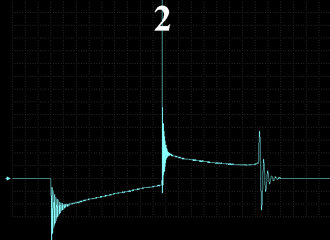
Figure 12. Secondary waveform of the serviceable compact individual ignition coil, received with help of the universal capacitive probe "Cx-M"
Presence of damped oscillations after breakdown of a spark interval between electrodes of a spark plug (the site is noted by a symbol "2") is consequence of design features of the coil and not an attribute of malfunction.
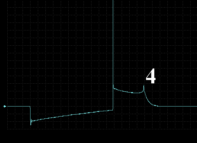
Figure 13. Secondary waveform of the faulty compact individual ignition coil, received with help of the universal capacitive probe "Cx-M"
An attribute of malfunction is absence of damped oscillations after the ending of burning of a spark between electrodes of a spark plug (the site is noted by a symbol “4”)
Time parameters of the ignition impulses (duration of energy accumulation in the magnetic field of the coil, the moment of occurrence of the spark, burning time of a spark) of the signal received with help of the universal capacitive probe “Cx-M” precisely corresponds to the real. The form of the signal repeats the secondary waveform of the diagnosed ignition system. Amplitude values of ignition impulses (a breakdown voltage of a spark interval, a burning voltage of a spark) depend of distance between the sensitive side of the capacitive probe and a secondary coil of the ignition coil – the less this distance, the more amplitude of a signal.
If the ignition control module is built-in to the compact individual ignition coil, in most cases the electric field created by a secondary coil of the ignition coil is in the metal screen, and reception of a signal with help of the capacitive probe is impossible. In this case, for diagnostics by the secondary voltage waveform applying the universal inductive probe "Lx-M".
Diagnostics by the secondary voltage waveform with help of the inductive probe
The inductive probe for diagnostics of the individual ignition coils by the secondary voltage waveform is the universal inductive probe "Lx-M". The inductive probe at diagnostics by the secondary voltage waveform is applied when reception of a signal with help of the capacitive probe is impossible. Such ignition coils mostly are rod individual ignition coils, compact individual ignition coils with the built-in ignition control module, and the individual ignition coils incorporated in modules.

Figure 14. Rod individual ignition coils
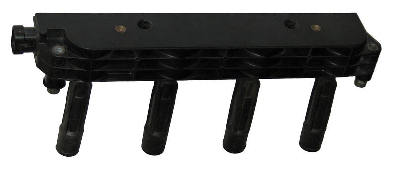
Figure 15. The ignition module consisting of four rod individual ignition coils
For diagnostics of the individual ignition coil by the secondary voltage waveform with help of the universal inductive probe "Lx-M"
- the socket of the probe must be connected to the input In+ or In- (depending on the polarity of the signal received) located on the front side of the USB Autoscope IV
- start the engine
- in the "USB Oscilloscope" program, select "Modes => Ignition => COP"
- put universal inductive probe "Lx-M" to the diagnosed ignition coil

Figure 16. Diagnostics of the rod individual ignition coil by the secondary voltage waveform with help of the universal inductive probe "Lx-M"
It is necessary to choose such position of the inductive probe "Lx-M" relatively of the core of the diagnosed ignition coil, at which in the window of the program "USB Oscilloscope" will be displayed the secondary voltage waveform of the diagnosed ignition coil.
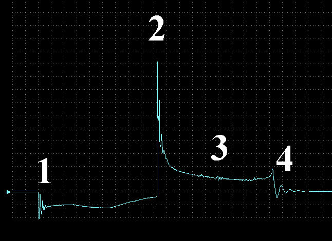
Figure 17. Secondary waveform of the serviceable rod individual ignition coil, received with help of the universal inductive probe "Lx-M"
- The beginning of accumulation of energy in the magnetic field of the ignition coil (coincides with the moment when the power transistor of the ignition control module turns on)
- Breakdown of a spark interval between electrodes of a spark plug and the beginning of spark burning (the moment when the power transistor of the ignition control module turns off)
- A site of a spark burning between electrodes of a spark plug
- The damped oscillations arising after of the ending of a spark burning between electrodes of a spark plug

Figure 18. Secondary waveform of the faulty rod individual ignition coil, received with help of the universal inductive probe "Lx-M"
An attribute of malfunction is absence of damped oscillations in the end of a spark burning between electrodes of a spark plug (the site is noted by a symbol "4").
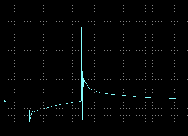
Figure 19. Secondary waveform of the faulty rod individual ignition coil, received with help of the universal inductive probe "Lx-M"
An attribute of malfunction is absence of damped oscillations in the end of a spark burning between electrodes of a spark plug and very short time of a spark burning.

