USB Autoscope IV
The USB Autoscope is a new generation of automotive diagnostic oscilloscope and engine analyzer. The device is designed for displaying, recording, and analyzing signals from most all vehicle systems such as:
Sensors and actuators;
Ignition systems;
Fuel delivery systems;
Intake and exhaust systems;
Engine mechanicals such as cylinders, valvetrains, and pistons;
Alternators, starters, glow plugs, batteries …
USB Autoscope IV is the most advanced oscilloscope/engine analyzer from our series of 8-channel analyzers.
The scope gets its power from the USB port. Some of the probes, such as the transducers, need external power and they will receive that from the vehicle battery. For this, USB Autoscope IV uses custom 3 pin connectors to provide power to the end of the test lead to power various accessories.
The test lead probes work without an external supply, but if you connect the oscilloscope to battery power, the Led in the probes will light up. That is a very nice feature when you try to back probe something or another and the light is not in your favor.
To power accessories the scope needs to have the 4 pin power supply cable hooked up to a power source, such as the vehicle’s battery. Ignition system testing capabilities are built in to the scope.
The different inputs of the USB Autoscope IV are designed for different input voltages. The first 4 connectors located on the front panel of the device are analog inputs №1…4. They have 2 input voltage ranges: ±6 V and ±30 V. The ±6V input is designed to measure the signal from the transducers supplied with the device; the ±30V input is designed to measure signals of low-voltage automotive sensors, as well as for measuring voltages in the vehicle's power circuits.
The 5th and 6th connectors are analog inputs №5 and №6. Other input voltage ranges are provided for them: ±60 V and ±300 V. These inputs are designed to measure signals from inductive rotational speed sensors, such as a crankshaft, camshaft, vehicle speed sensor, shaft speed sensors in a gearbox, wheel speed sensors, a diesel fuel pump shaft, a turbocharger, as well as for measuring signals from other sensors that generate an increased voltage. Also, these inputs are designed to measure voltage waveform of control signals for ignition coils, fuel injectors, and other electronically controlled actuators.
Connectors 7, 8 and 9 on the front panel of the device are designed to connect capacitive and inductive high-voltage probes for testing ignition systems.

Front panel elements
Connections for analog inputs 1…4. Input voltage range ± 6 / 30 V |
|
Connections for analog inputs 5…6. Input voltage range ± 60 / 300 V |
|
Connections "In+" and "In-" 3 are used for connection of high voltage probes.The signals from the high voltage probes are inversely summed and go to the analoginput 8 |
|
8 |
Connection "In Synchro" 3 is used for the synchronization (trigger) transducer that isused to detect ignition spark. The signal from the transducer goes to the analog input 7 through a peak detector |
10 |
Transducers' power indicator. Works only when the "12V" input is powered |
Pulse polarity indicator from synchronization transducer |

Back panel elements
1 |
12 V connection. Used for powering certain transducers that are connected to the inputs. Connects to the diagnosed vehicle battery through the power supply cable |
2 |
Ignition connection. Analog inputs 7, 8 |
3 |
USB connection. Used for connection of the USB Autoscope IV to USB 2.0 480 Mbit/s (HI- SPEED) port of a laptop or PC. The connection uses a USB 2.0 type A-B cable |
4 |
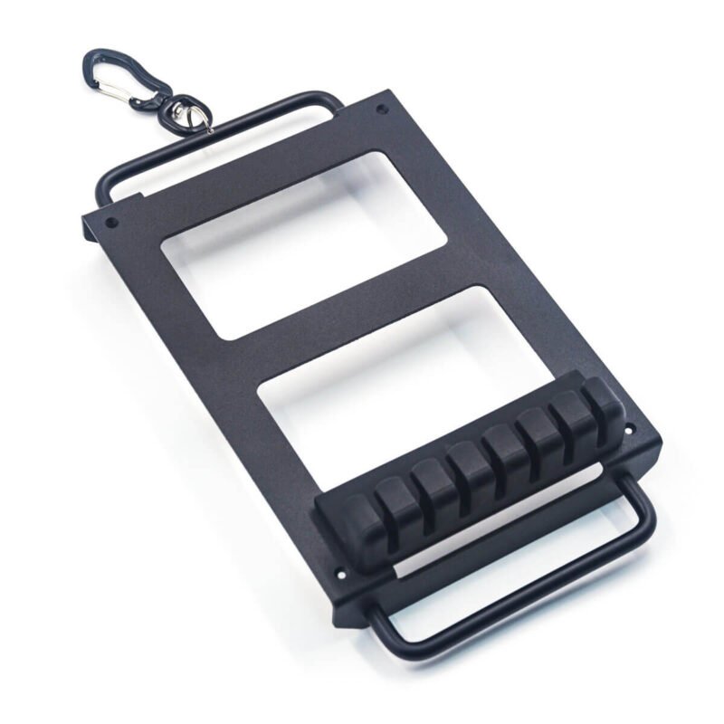
Spacer for attaching of USB cable hanger |
5 |
Device ground terminal |
6 |
USB status indicator |
Technical characteristics
Parameter |
Value |
|---|---|
Number of analog inputs |
8 |
Voltage range (switchable, two ranges) |
|
analog inputs 1…4 |
±6 / 30 V |
analog inputs 5, 6 |
±60 / 300 V |
analog inputs 7, 8 |
±6 V |
Input impedance |
1 MΩ |
ADC resolution |
12 bit |
Oversampling ADC resolution |
up to 16 bits |
Maximum sampling frequency for channel |
|
in 1 channel sub mode |
12.5 MHz |
in 2 channel sub mode |
5.0 MHz |
in 4 channel sub mode |
2.5 MHz |
in 8 channel sub mode |
1.25 MHz |
The nominal signal digitizing depth is 12 bit, increasing up to 16 bit with slower digitizing speeds. |
|
General
Parameter |
Value |
|---|---|
Operating system |
Windows 7, Windows 8, Windows 10, Windows 11 |
Current consumption from USB |
no more than 300 mA |
Current consumption of the “12V” input |
no more than 1 A |
Device provides uninterrupted (seamless) data transfer of digitized data to the laptop or PC. |
|
The stream of digitized data is stored directly on the hard disk of the laptop or PC in real time. |
|
Download
| USB Autoscope IV User Manual | |
| USB Oscilloscope Software ver. 4.4.9.83 Beta | |
| Software user manual |