ElPower script Manual
The “ElPower” script is used for automatic analysis of battery voltage and current waveforms in order to obtain a fast and comprehensive diagnostic of vehicle starting and charging systems, as well as to measure the relative compression of the cylinders of gasoline and diesel engines. The script in conjunction with the oscilloscope is providing an advanced report on the battery, alternator and starter condition together with a relative compression in the engine cylinders. Additionally, other high-power electrical consumers may be analyzed very quickly.
Purpose
The ElPower script is designed to diagnose the vehicle starting and charging system, as well as to measure the relative compression of the cylinders of gasoline and diesel engines. It allows you to check the characteristics and condition of these vehicle components and systems:
- battery
- glow plugs of a diesel engines
- starter
- relative compression in the engine cylinders (can be measured without the use of a current clamp)
- alternator
In the process of analyzing the voltage waveform at the battery terminals and the current waveform obtained through the use of a current clamp, the ElPower script generates multiple report tabs, where it displays a number of the measured and calculated characteristics of the system components. It also provides an assessment of the consistency of the battery characteristics with the characteristics of the starter. If it detects any deviations or malfunctions, the script automatically displays appropriate messages.
Recording the waveforms
To get the most informative and complete report of the ElPower script, you should adhere to the recommendations outlined here. If the current clamp is not used during the test, the script will be able to measure only the relative compression. The rest of the functionality will be available only if using a current clamp.
To obtain the current waveform, use a non contact DC clamp with a sensitivity of 1 mV/A and a measuring range of at least ±1000 A. For testing the charging system of small non automobile engines, which are started with a low power electric starter, it is optimal to use clamps operating with a sensitivity of 10 mV/A and a measuring range of ±100 A. Recommended clamp models that meet these requirements are: APPA 32 / APPA 36T / APPA 39T.
Connection order for USB Autoscope IV
- Connect to the "–" terminal of the vehicle battery the black alligator clip, part of the USB Autoscope IV power cord
- The measuring adapter, using a small alligator clip, connects to the terminal "+" of the battery and connects to input #1 of the USB Autoscope IV
- Connect the current clamp to input #4 of the USB Autoscope IV using a PIN3 Banana adapter. Move the switch on the current clamp to the "600A 1mV/A (1000A 1mV/A)" setting
Connection order for USB Autoscope Lite
- Connect oscilloscope probe to the input #5 of the USB Autoscope Lite. The black alligator clip connects to terminal "–" of the vehicle battery, the lead of the oscilloscope probe to terminal "+"
- Connect the current clamp to input #2 of the USB Autoscope Lite using BNC Banana adapter. Move the switch on the current clamp to the "600A 1mV/A (1000A 1mV/A)" setting
Waveforms recording
- In the USB Oscilloscope program choose "Modes => ElPower => ElPower"
- Position the current clamp so the jaw surrounds all of the wires emanating from one of the battery terminals. Orient the current clamp so the "+" mark points in the direction of the current flow using the conventional theory of current flow
- Perform zero calibration by turning the potentiometer on the current clamp body. Adjust until the signal from the current clamp is in the middle of the red zone on the oscilloscope screen (or press zero button).
This should be done before starting the waveform recording! - Start the waveform recording by pressing the "Record" button on the USB Oscilloscope program
- Close the jaws to embrace all the wires emanating from one of the battery terminals (jaw tightly)
- Turn the high beam headlights on for 3…5 seconds, then turn them off. In case of difficulty, instead of high beam headlights can be switched on turn signal lamps
- Turn on the ignition
- Wait a few seconds for the fuel pump to shut back off. If the vehicle is equipped with a diesel engine, wait for the glow plugs to shut off
- Start the engine (If the engine does not start, continue cranking for 5 to 10 seconds)
- After 5 to 10 seconds, turn the high beam headlights back on for 3 to 5 seconds (or turn signal lamps)
- After another 3 to 5 seconds, turn off the ignition
- Remove the current clamp from the power wires and bring the jaws directly to the power wire from the battery terminal. Place the clamp in a position close to the one in which the measurements were taken
- Turn off the recording by clicking the "Stop" button on the USB Oscilloscope screen.
This action must be performed after removing the clamp from the power wires! - If necessary, the recorded waveform can be saved using the "File => File save"
How to measure relative compression
Connection of a current clamp is optional to measure the relative compression. The rest of the ElPower script functionality will be available only with a current clamp.
The connection procedure here is similar to the standard . But an additional requirement is added: it is necessary to create conditions in which the engine will not start when cranking with the starter (as in the classic compression measurement). In this case, one of the two methods outlined below should be adhered to.
Simplified procedure (measuring only relative compression)In addition to checking the relative compression in the engine cylinders, a simplified procedure also allows you to check the starting and charging system of the car, with the exception of the alternator.
- Stop the engine from starting by disconnecting the fuel injector fuse or otherwise
- Connect the equipment in accordance with paragraph 2.1; however, the connection of the current clamp is optional
- Call the "Modes => ElPower…" menu and start signal recording
- Crank the engine with a starter for 5…10 seconds
- Stop signal recording
- Call the "Analysis => Execute script" menu. In this case, the conditions necessary for switching the ElPower script to the online version of the algorithm should be provided, which are described in paragraph 3.3
An advanced procedure allows during one measurement to check not only the relative compression in the engine cylinders, but also the entire starting and charging system of the car.
- Stop the engine from starting by switching off the fuse of its control system using the Remote Power Off fuse switch

- In the USB Oscilloscope window, open the "Modes => ElPower => ElPower" menu
- Bring the jaws close to the power wire emanating from one of the terminals of the battery, and position the clamp to this terminal with the side, which polarity designation coincides with the polarity on the battery terminal
- Calibrate zero – by rotating the calibration wheel on the clamp body, achieve the position of the signal to the center of the red zone on the oscilloscope screen (or press the automatic zero calibration button). This action must be performed before starting signal recording!
- Start the waveform recording by pressing the "Record" button on the USB Oscilloscope window
- Close the jaws to embrace all the wires emanating from one of the battery terminals (jaw tightly)
- Turn the high beam headlights on for 3…5 seconds, then turn them off. In case of difficulty, instead of high beam headlights can be switched on turn signal lamps.
- Switch off the fuse for the engine control system
- Turn on the ignition, wait a few seconds for the fuel pump to shut back off. If the vehicle is equipped with a diesel engine, wait for the glow plugs to shut off
- Crank engine for 3…5 seconds and then switch on the engine control fuse
- After 5 to 10 seconds, turn the high beam headlights back on for 3 to 5 seconds (or turn signal lamps)
- After another 3…5 seconds, turn off the ignition
- Remove the current clamp from the power wires and bring the jaws close to the power wire from the battery terminal. Place the clamp in a position close to the one in which the measurements were taken
- Turn off the recording by clicking the "Stop" button on the USB Oscilloscope window. Perform this action only after removing the clamp from the power wires!
- If necessary, the recorded waveform can be saved using the "File => File save"
Starting the script
Configuration window
To start the analysis of recorded signals, in the USB Oscilloscope program window, call the menu "Analysis => Execute script". The "Please enter value(s)" configuration window will be displayed on the computer screen.
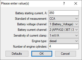
In the window "Please enter value(s)" choose / enter some values as follows:
- battery starting current and standard of measurement (this information can be found stamped or written on the top or side of the battery housing)
- engine type
- number of engine cylinders / firing order
- timing cylinder number
Signal analysis by the script algorithm will start after clicking the "OK" button.
Working with the offline version of the algorithm
The ElPower script is constantly being developed and improved, and new functions are continuously being added. This improves the accuracy and information content of the results obtained, but also leads to an increase in the amount of mathematical calculations performed each time during signal analysis. This increases the amount of time it takes to complete the analysis. Therefore, when creating an offline version of a script algorithm, programmers have to take into account the limited computing power and disk space of the user's computer and apply simplified algorithms in order to make the analysis fast.

The ElPower script automatically switches to the offline version of the algorithm if the online version cannot be launched.
Working with the online version of the algorithm
The online version of the script algorithm is executed not on the central processor of the user's computer, but by means of a remote server. The computing power of the server is much higher than the power of the personal computer, which allows programmers to significantly complicate the analysis algorithms. This significantly improves the accuracy of the results. In addition, this expands the functionality of the script, in particular, made it possible to create a rather complex algorithm for calculating the relative compression in the cylinders of internal combustion engines, measured by the starter current and / or by the voltage at the battery terminals. This functionality is included in the online version of the ElPower script algorithm.

Different modes of the engine work in the "efficiency" tab
The ElPower script switches to the online version of the algorithm only if there is a stable Internet connection and an access key to server.
First launch of the online version of the algorithm
When you start the online version of the ElPower script algorithm for the first time, you will need an access key to the server. In order to get it, you need to register on the website waveform-analyzer.com, where you will be provided with 3 copies of the access key.
Copy any of them and enter in the corresponding field of the "Authorization on the server waveform analyzer.com" window, which the USB Oscilloscope program will display on the screen at the right time (the other two keys allow you to connect your other computers to the server).

After entering the key, the script will automatically switch to the online version of the algorithm.
The script report
The report from the offline version of the algorithm
When working with the offline version of the ElPower script algorithm, the analysis results are displayed directly in the USB Oscilloscope program window. The script report consists of several tabs. The measured and calculated characteristics of the components of the engine starting and charging system are displayed in the "Analysis Results" tab.

The "Graphs" tab displays smoothed graphs of battery voltage and current, as well as graphs of calculated (estimated) generator currents and consumption by the on board network.
The report from the online version of the algorithm
When working with the online version of the ElPower script algorithm, the analysis results are displayed using the Reports Viewer program, the installation package of which must be downloaded from the link below and installed – https://waveform-analyzer.com/downloads
The script report obtained using the online version of the algorithm displays the same data as in the report of the offline version of the algorithm; but here they are more accurate and reliable.
Also, in the report from the online version of the ElPower script algorithm, the "Compression" tab may be displayed, provided that the algorithm was able to calculate the data required for its construction.

The individual compression values are displayed here as bar graphs. Each bar graph corresponds to one individual compression cycle of the cylinder. The columns are grouped by cylinders.
Contents of the "Results of analysis" Tab
The results are grouped in the following order
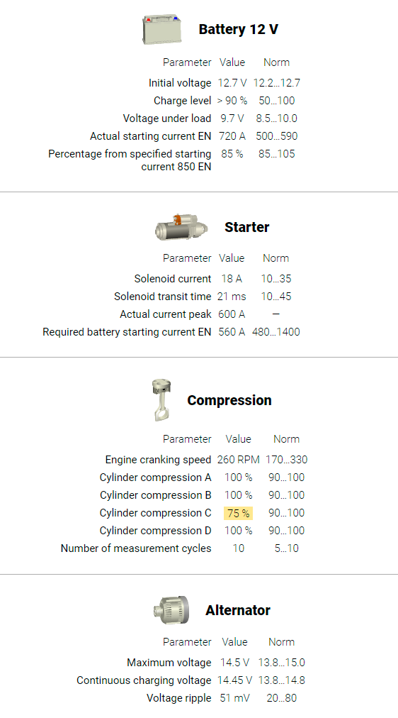
Battery
- Initial voltage – measured battery voltage at the start of measurement. For best results, the battery should be fully charged and the vehicle should be allowed to rest for one hour before testing
- Charge level – calculated on the basis of the initial voltage. For best results, the battery should be fully charged and the vehicle should be allowed to rest for one hour before testing
- Voltage under load – actual voltage under load at the time of the peak current consumption, which is while the engine is being cranked. The voltage under load should not drop below 9 V. Less than 7 V can cause hard starting and various malfunction problems with the on board electronics
- Actual starting current - the amount of current that can be safely taken from the battery; if this value is not exceeded, then the voltage drop at the battery terminals will be within the permissible value (in the "Norm" column, the value of the battery starting current is displayed, which is required for the normal operation of the starter of this particular vehicle
- Percentage from specified starting current – displays the ratio of the battery current capacity compared to the rating on the battery housing. If the value is less than 50 %, the battery is typically bad
Glow plugs
- Total peak current of all glow plugs – the peak value of the current consumed from the battery by the diesel engine glow plugs when they are turned on
- Glow plug on time – time from turn on and until turn off
- Probable number of faulty glow plugs – estimated number of «blown» glow plugs
Compression
- Engine cranking speed – average value of engine RPM during engine cranking
- Cylinder compression… – measured value of relative compression
- Number of measurement cycles – the number of measurements of the relative compression value for each of the cylinders
Starter
- Solenoid current – total current of pull in and hold in windings of the starter solenoid. (This measurement is done before the starter main contact is closed)
- Solenoid transit time – time from the solenoid is turned on and until the power contacts close. Increased time and / or large variances of this measurement may indicate a «sticking» solenoid or armature
- Actual current peak – the largest current value seen, as the starter is engaged
- Required battery starting current – the calculated value of the cranking current that the battery must provide so that the voltage at its terminals does not drop below 9 V
If the calculated value of the nominal peak current is near the lower limit, the starter cables may be of insufficient thickness, a bad contact in the starter circuit, or too much electrical resistance in the starter. If this value is near the upper limit – then use of a larger battery is recommended.
- Starter current drop outs occur due to wear of the brushes and / or the commutator bars. This failure creates significant interference in the vehicle electrical system and can lead to malfunction of the electronics or even make starting the engine very difficult
Alternator
- Maximum voltage – maximum battery voltage seen. Voltage more than 16 V can cause various malfunction problems with the on board electronics
- Continuous charging voltage. If the charging voltage is below 13.8 V, incomplete charging can occur. If the voltage is above 15 V, damage to the battery and possibly to the vehicle electronics can occur
The reason for the low charging voltage can be a generator malfunction or higher than normal current consumption in the vehicle. For example, some diesel engine control units cycles the glow plugs after engine start for a few minutes. Total current consumption, thus, can exceed the maximum current capacity of the generator.
- Voltage ripple – larger values may indicate a problem with the diode bridge or stator of the generator
- Current of one phase is missing. This message appears when one phase of the generator is not working
The "Graphics" tab
It displays smoothed graphs of the measured battery current and voltage, which, if necessary, can be used for additional measurements in manual mode.

In addition graphs of calculated (estimated) alternator current and on board consumption are provided.